
Method for regulating stress of multi-component laser cladding layer

A laser cladding and multi-component technology, which is applied in coating, metal material coating process, etc., can solve the problems of cladding layer cracking, brittleness, and cladding layer stress, etc., and achieve the effect of preventing cracks

Inactive Publication Date: 2020-03-24
BEIJING UNIV OF TECH
View PDF5 Cites 2 Cited by
  • Summary
  • Abstract
  • Description
  • Claims
  • Application Information

AI Technical Summary

Problems solved by technology

However, when using laser cladding technology to prepare FeCrNiAlCoTi alloy cladding layer, it is found that due to the high hardness and brittleness of FeCrNiAlCoTi alloy, the stress in the obtained cladding layer is too large, which makes the cladding layer crack seriously and cannot meet the requirements for use.

Method used


Image

  • Method for regulating stress of multi-component laser cladding layer
  • Method for regulating stress of multi-component laser cladding layer
  • Method for regulating stress of multi-component laser cladding layer

Examples


Embodiment 1

[0033] (1) Put the high-purity metal elemental powder Fe, Cr, Ni, Al, Co and Ti in the smelting furnace for arc melting to obtain the original ingot, and put the original ingot into the gas atomization powder making equipment Melting, while passing argon gas to form an impact on the melt, the melt is impacted and dispersed to form small droplets, and after cooling, the required FeCrNiAlCoTi pre-alloyed powder is formed, and the powder particle size is 58-130μm.

[0034] (2) Add Cr with a particle size of 58-130 μm to the FeCrNiAlCoTi pre-alloyed powder 3 C 2 Ceramic powder, mechanically mixed evenly and then dried, put into the coaxial synchronous powder feeder for use, wherein, Cr in the mixed alloy powder 3 C 2 The mass percentage of ceramic powder is 10%;

[0035] (3) Aim the laser head of the laser at the surface of the 42CrMo alloy steel;

[0036] (4) Through the coaxial synchronous powder feeder of step (1), the alloy powder is evenly and continuously sent to the sur...

Embodiment 2

[0042] The difference between embodiment 2 and embodiment 1 is only: Cr in the mixed alloy powder of embodiment 2 3 C 2 The mass percentage of ceramic powder is 12%; the laser coating process parameters are: laser power 1600W, scanning speed 7mm / s, spot diameter 4.5mm, argon gas flow rate 18L / min, powder feeding rate 8g / min, the overlap rate is 35%.

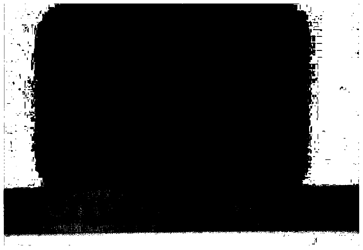
[0043] Figure 5 Be the metallographic diagram of embodiment 2 cladding layer, from Figure 5 It can be seen that there are no microcracks in the cladding layer, and the TiC particles generated by the in-situ reaction are evenly distributed.

Embodiment 3

[0045] The difference between embodiment 3 and embodiment 1 is only: Cr in the mixed alloy powder of embodiment 3 3 C 2 The mass percentage of ceramic powder is 14%. The laser coating process parameters are as follows: laser power is 2000W, scanning rate is 9mm / s, spot diameter is 4.5mm, argon gas flow rate is 20L / min, powder feeding rate is 12g / min, the overlap rate is 40%.


PUM


Abstract

The invention relates to the technical field of laser cladding surface strengthening, in particular to a method for regulating stress of a multi-component laser cladding layer. The method comprises the following steps of adding Cr3C2 ceramic powder into a Ti-contained multi-component pre-alloy powder for laser cladding. The invention further provides a laser cladding method, and the preferred process parameters in the method are that the laser power is 1400 to 2000 W, and the scanning rate is 4 to 9 millimeter per second, the spot diameter is 4 to 6 millimeter, and the argon flow is 15 to 20 liter per minute, the powder feeding rate is 8 to 12 gram per minute, and the lap rate is 35% to 50%. According to the method for regulating the stress of the multi-component laser cladding layer, through adding the Cr3C2 ceramic powder into the Ti-contained multi-component pre-alloy powder, in-situ reaction is carried out to improve the fracture toughness of the cladding layer, the residual stressin the cladding layer is reduced, and meanwhile, the wear resistance and corrosion resistance of the cladding layer are improved.

Description

technical field [0001] The invention relates to the technical field of laser cladding surface strengthening, in particular to a method for regulating the stress of a multi-component laser cladding layer, a laser cladding method and a multi-component laser cladding layer. Background technique [0002] As a multi-component alloy, FeCrNiAlCoTi has the advantages of high hardness (~750HV) and good corrosion resistance. It can be prepared as a coating to significantly improve the wear resistance and corrosion resistance of the substrate (such as carbon steel, alloy steel, etc.). properties, thereby effectively protecting the substrate. Laser cladding (Laser cladding), as an advanced processing technology, has significant advantages such as high bonding strength and low dilution rate, and has been widely used in the preparation of various protective coatings. However, when the FeCrNiAlCoTi alloy cladding layer was prepared by laser cladding technology, it was found that due to th...

Claims


Application Information

Patent Timeline
IPC IPC(8): C23C24/10C22C30/00C22C32/00
CPCC22C27/06C22C30/00C22C32/0052C23C24/103
Inventor 周正黄杰贺定勇郭星晔谈震吴旭王曾洁邵蔚王国红崔丽
Owner BEIJING UNIV OF TECH
Learn More