Laser cladding method of shaft and tube element

A laser cladding and cladding technology, which is applied in the direction of machine tools designed for grinding the rotating surface of workpieces, grinding/polishing equipment, surface polishing machine tools, etc. Low-level problems, to achieve the effect of simplifying machining procedures, improving cladding efficiency, and improving processing efficiency

Pending Publication Date: 2019-11-22
SHANDONG ENERGY HEAVY EQUIP GRP DAZU REMANUFACTURING CO LTD
View PDF5 Cites 6 Cited by
  • Summary
  • Abstract
  • Description
  • Claims
  • Application Information

AI Technical Summary

Problems solved by technology

However, over the years, it has not been able to replace chrome plating in a real sense. The reason is that processing costs, processing accuracy, processing efficiency and other issues limit its further promotion and application, and the improvement of processing efficiency is the technical bottleneck.
[0003] The processing efficiency of the existing laser cladding technology is low, and the efficiency has become the main factor restricting the popularization and application of this technology, which leads to high processing costs and cannot completely replace electrochrome plating; at the same time, the processing accuracy of the existing technology is low, and it is difficult to produce small-sized, precise The surface of the parts is processed by laser cladding, and the existing technology has a large heat input and a large dilution rate, which leads to deformation of the parts, making it difficult to complete cladding processing such as shafts and pipes, and difficult to achieve titanium, aluminum, copper, etc. Laser processing of the surface of the material; moreover, the existing technology is mostly cladding and forming with a large thickness, and the subsequent mechanical processing removes a large amount and the material waste is serious

Method used


Image

  • Laser cladding method of shaft and tube element
  • Laser cladding method of shaft and tube element
  • Laser cladding method of shaft and tube element

Examples


Embodiment 1

[0041] A laser cladding method for a column, the specific steps are as follows:

[0042] S1: Processing and testing before cladding. Machining the column, testing the original specification size, and leaving a machining allowance according to the technical requirements. The machining allowance is generally the diameter after cladding minus the diameter of the final product, and the machining allowance in this embodiment is not less than 0.2mm.

[0043] S2: Surface pretreatment, degreasing the column to ensure the bonding between the cladding layer and the substrate. Specifically, use alcohol to wipe and sandpaper to polish the area to be clad to remove rust, oil and dirt.

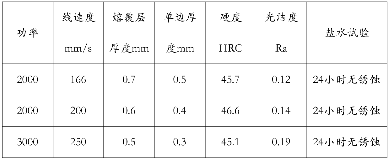
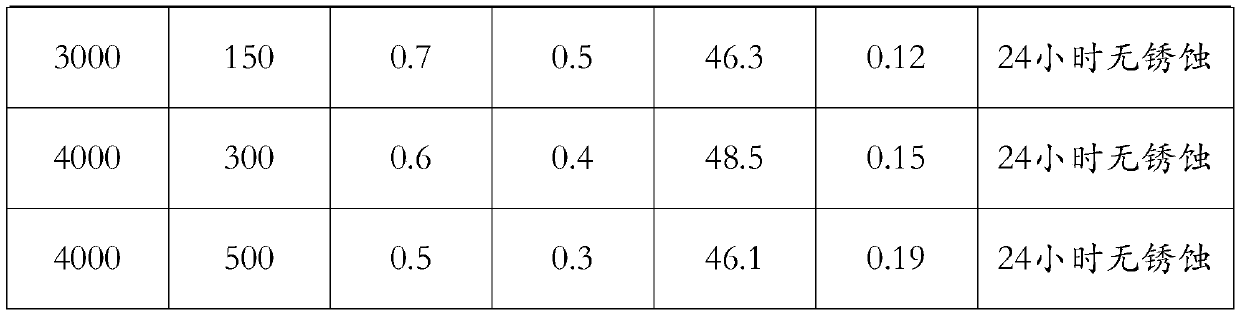
[0044] S3: Laser cladding. Place the column on the lathe, use elastic thimbles to clamp the column, and perform positioning and alignment. The laser processing system in this embodiment uses coaxial powder feeding. First, set the laser cladding parameters, including cladding power of 2000W and laser spo...

Embodiment 2

[0059] A laser cladding method for a mandrel, the specific steps are as follows:

[0060] S1: Processing and testing before cladding. The cladding part is the overall outer surface of the mandrel, the diameter of the mandrel in the cladding area is Φ180.3mm, the length of the cladding area is 11m, and the cladding surface area is 6.3m 2 ; After confirming the state of the mandrel, straighten the workpiece, and the concentricity is ≤0.2mm; use a lathe to turn the surface of the mandrel. The turning process includes rough turning and fine turning. The speed is 40mm / min, the turning speed of the lathe is set at 150r / min, and the feed rate is 20mm / min, and the fatigue layer on the surface of the mandrel is removed by turning to obtain a surface roughness ≤ Ra6.3; finally, the flaw detection of the workpiece is carried out to check the surface of the mandrel Whether there are pores or crack defects, the next step can be performed only after the entire flaw detection is qualified. ...

Embodiment 3

[0073] A high-speed laser cladding method for boiler tubes, the specific steps are as follows:

[0074] S1: Processing and testing before cladding. Machining the boiler tubes, testing the original size, and leaving a machining allowance according to the technical requirements. The machining allowance is generally the diameter after cladding minus the diameter of the final product, and the machining allowance in this embodiment is not less than 0.2mm.

[0075] S2: Surface pretreatment, degreasing the workpiece to ensure the bonding between the cladding layer and the substrate. Specifically, use alcohol to wipe the area to be clad to remove rust, oil and dirt.

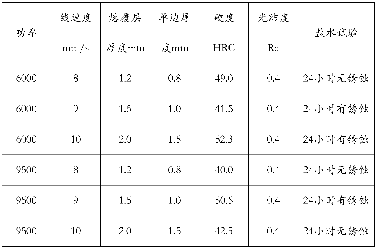
[0076] S3: Laser cladding. Firstly, the boiler tube to be processed is placed on the lathe, clamped with a positioner, and positioned and aligned; then the robot grabs the laser and advances along the axis of the boiler tube with a step distance of 0.5mm, and the positioner drives the boiler The tube realizes the rot...


PUM

PropertyMeasurementUnit
Concentricityaaaaaaaaaa
Thicknessaaaaaaaaaa
Pore diameteraaaaaaaaaa

Abstract

The invention discloses a laser cladding method of a shaft and tube element. The shaft and tube element comprises but is not limited to a column, a core rod and a boiler tube. The laser cladding method comprises the following steps: 1, carrying out machining or detecting before cladding; and 2, carrying out laser cladding. According to the laser cladding method, cladding linear velocity is higher,a cladding layer can be rapidly prepared within a short time, and the cladding efficiency is remarkably improved; and meanwhile, the heat effect is small, high-precision forming on the surface of a workpiece can be obtained, subsequent machining removal amount is reduced, machining programs are simplified, material consumption is reduced, and the machining efficiency is improved.

Description

technical field [0001] The invention relates to the technical field of laser cladding, in particular to a laser cladding method for shafts and pipes. Background technique [0002] The surface treatment technology has created great practical value since its application, realizing the recycling of remanufacturable parts and prolonging the service life of reinforcement parts. Traditional application processes such as hard chrome plating, thermal spraying, surfacing, etc., have their own technical limitations. The emergence of laser cladding has greatly expanded the application field of surface treatment technology, improved processing efficiency and processing quality. However, over the years, it has not been able to replace electrochrome plating in a real sense. The reason is that processing costs, processing accuracy, processing efficiency and other issues limit its further promotion and application, and the improvement of processing efficiency is the technical bottleneck. ...

Claims


Application Information

Patent Timeline
IPC IPC(8): C23C24/10C22C38/54C22C38/44C22C38/04C22C38/02C22C38/52C22C19/05B24B5/04B24B29/04
CPCB24B5/04B24B29/04C22C19/056C22C38/002C22C38/02C22C38/04C22C38/44C22C38/52C22C38/54C23C24/103
Inventor 澹台凡亮田洪芳杜学芸郎坤李光浩杨帆王伟侯庆玲翟勋富张岩
Owner SHANDONG ENERGY HEAVY EQUIP GRP DAZU REMANUFACTURING CO LTD
Why Eureka
Try Eureka