
Laser composite repair method for surface corrosion of inner hole of shell

A composite repair and inner hole technology, which is applied in laser welding equipment, coating, metal material coating process, etc., can solve the problem that the inner hole surface roughness and air tightness test are difficult to meet the requirements, and the inner hole repair is difficult to implement laser cladding. It is difficult to accurately deliver the cladding powder to the repaired part, etc., so as to achieve the effect of small thermal deformation, small thermal influence and thermal damage, and improve the repair quality

Inactive Publication Date: 2019-11-19
国营芜湖机械厂
View PDF4 Cites 2 Cited by
  • Summary
  • Abstract
  • Description
  • Claims
  • Application Information

AI Technical Summary

Problems solved by technology

With the existing micro-arc deposition method, there are many micropores in the repair layer, and the surface roughness and air tightness test of the repaired inner hole are difficult to meet the requirements. Due to the limited inner hole diameter of the part, it is difficult to accurately clad the powder by using the laser cladding repair method. Delivery to the repair site
"Thermal Processing Technology", Volume 41, Issue 20, Pages 111-114, published in 2012, discloses the research on laser cladding-micro-arc spark deposition composite repair technology, the purpose of which is to use the micro-arc spark deposition process to obtain A layer of intermediate transition layer, and then use laser cladding on the intermediate coating to prepare the coating with the required properties of the substrate. The disadvantage is that it is difficult to implement laser cladding powder feeding for inner hole repair, and there is no clear solution to inner hole corrosion. The specific method of repair

Method used


Image

  • Laser composite repair method for surface corrosion of inner hole of shell

Examples


Embodiment Construction

[0027] In order to make the technical means, creative features, goals and effects achieved by the present invention easy to understand, the present invention will be further elaborated below in conjunction with the accompanying drawings and embodiments.

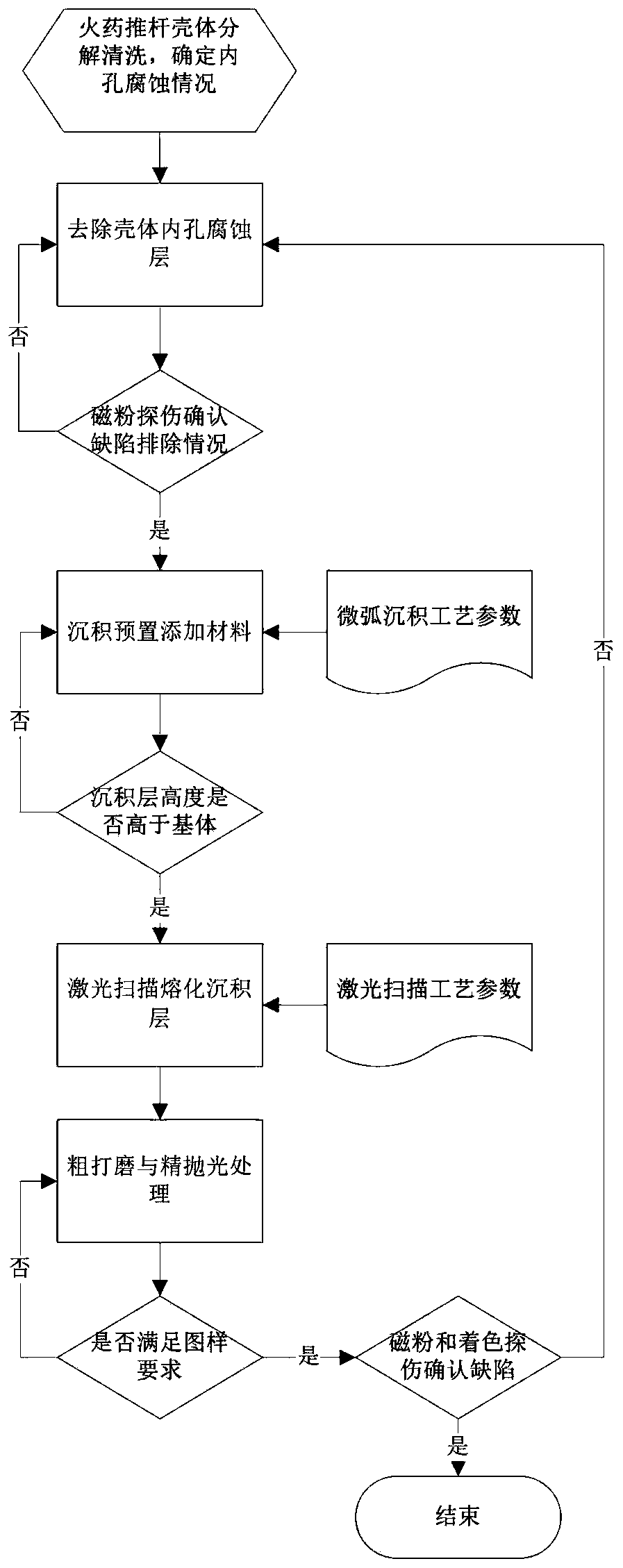
[0028] Such as figure 1 As shown, a laser composite repair method for the surface corrosion of the inner hole of the shell includes the following steps:

[0029] (1) Decompose and clean the surface of the inner hole of the gunpowder push rod shell, measure the size, and determine the local corrosion position and corrosion amount of the inner hole.

[0030] (2) According to the test results, the shell of the propellant push rod is analyzed and its life is evaluated, and the corrosion layer in the inner hole of the shell is removed.

[0031] (3) Use magnetic particle inspection to ensure that there are no crack defects after removing the corrosion layer. If there are crack defects, repeat step (2) until it is ensured that ther...


PUM

PropertyMeasurementUnit
diameteraaaaaaaaaa

Abstract

The invention relates to a laser composite repair method for surface corrosion of an inner hole of a shell. The laser composite repair method comprises the following steps of disassembling and cleaning the surface of an inner hole of a powder push rod shell, and measuring the dimensions; determining the local corrosion part and corrosion amount of the inner hole; analyzing the powder push rod shell and evaluating the life of the powder push rod shell according to the detection results, and removing the corrosion layer of the inner hole of the shell; and adopting magnetic particle testing, andensuring that no crack defects occur after removal of the corrosion layer. By adopting preset additive materials of microarc deposition GH4169 corrosion resistant metal bars, the trouble that powder is hard to reach the repair part of the inner hole in a laser cladding feeding mode is overcome; by adopting a microarc deposition and laser scanning composite processing mod, a specific method for corrosion repair of the inner hole is formed; beneficial reference is provided for damage repair of the inner hole, and the repair method has the advantages of low heat input amount and thermal deformation amount, and less heat effect on and heat damage to metal base; and the repair quality of the inner hole of the shell can be improved obviously.

Description

technical field [0001] The invention relates to the technical field of laser cladding, in particular to a laser composite repair method for surface corrosion of inner holes of shells. Background technique [0002] The material of the aircraft propellant push rod shell parts is 30CrMnSiA. Due to the influence of the propellant storage environment during its long-term service, local corrosion failures in the inner hole with a diameter of 50mm have occurred, and appropriate methods need to be used to repair it. With the existing micro-arc deposition method, there are many micropores in the repair layer, and the surface roughness and air tightness test of the repaired inner hole are difficult to meet the requirements. Due to the limited inner hole diameter of the part, it is difficult to accurately clad the powder by using the laser cladding repair method. Delivered to repair site. "Thermal Processing Technology", Volume 41, Issue 20, Pages 111-114, published in 2012, discloses...

Claims


Application Information

Patent Timeline
Patent Type & Authority Applications(China)
IPC IPC(8): C23C26/02B23K26/00B23K26/34C22C19/05
CPCB23K26/00B23K26/34C22C19/055C23C26/02
Inventor 张志强陈体磊程宗辉范朝唐喆
Owner 国营芜湖机械厂
Learn More