
360-DEG large visual field integrated bionic compound eye

A bionic compound eye and large field of view technology, applied in optics, lenses, instruments, etc., to achieve high repeatability, uniform array, and light weight

Inactive Publication Date: 2018-07-17
HANGZHOU POLYTECHNIC
View PDF9 Cites 5 Cited by
  • Summary
  • Abstract
  • Description
  • Claims
  • Application Information

AI Technical Summary

Problems solved by technology

It can realize all-round image capture or video monitoring and other functions

Method used


Image

  • 360-DEG large visual field integrated bionic compound eye
  • 360-DEG large visual field integrated bionic compound eye
  • 360-DEG large visual field integrated bionic compound eye

Examples


Embodiment example 1

[0037] The preparation method of the bionic cornea is as follows:

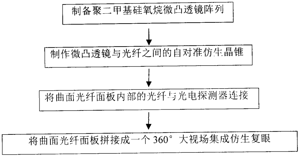
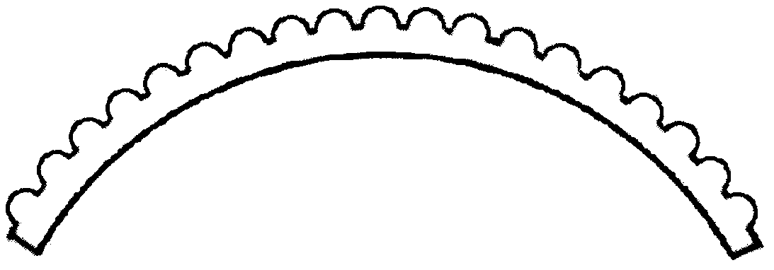
[0038] Use a curved fiber optic panel without optical fibers as a substrate, deposit polydimethylsiloxane on it, solidify and separate, and obtain a polydimethylsiloxane micro-convex lens array, such as figure 2 As shown, the bionic "cornea" constructed with this micro-convex lens array is completed.

[0039] After the above-mentioned micro-convex lens array is completed, it needs to be docked with a curved fiber optic panel with the same size and shape inserted with optical fibers to realize the integration of the micro-convex lens array and optical fibers, that is, the bionic cornea and the bionic optic nerve. When docking, use photosensitive resin for gluing. After gluing, connect the other end of the optical fiber in the fiber panel with a UV light source, expose the photosensitive resin on the end face of the optical fiber to ultraviolet light, and then post-bake the photosensitive resin, so that the pho...

Embodiment example 2

[0043] Using optical fiber polishing technology, laser micro-engraving, chemical corrosion, chemical deposition and other methods to process the end face of the optical fiber, a special optical fiber with a micro-convex lens structure is produced on the end face. The special optical fiber structure is as follows: Figure 4 shown. Insert special optical fibers into the curved fiber optic panel to obtain a fiber optic panel integrated with bionic cornea and bionic optic nerve.

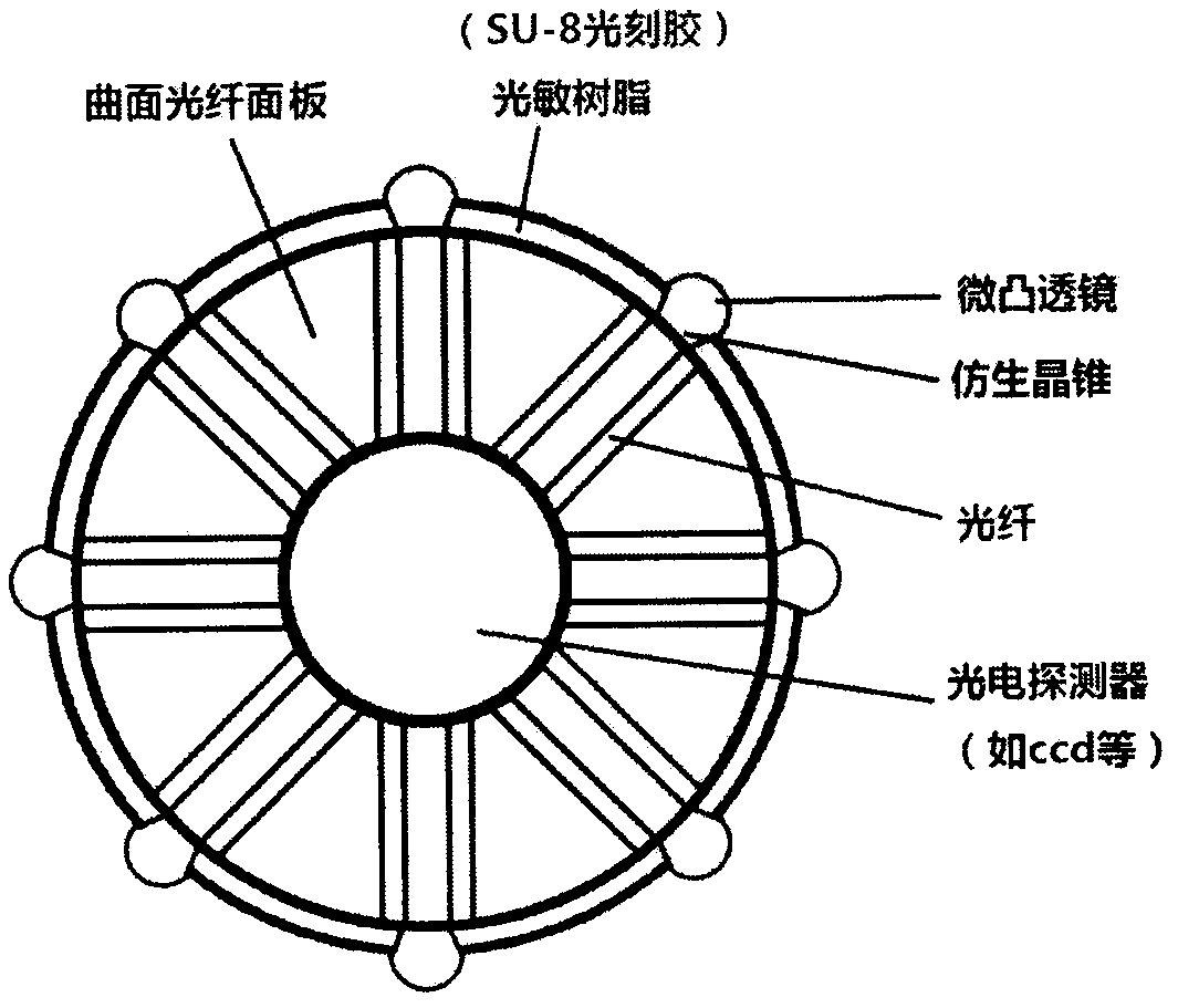
[0044] The spherical fiber optic panel is spliced ​​by curved fiber optic panels of different sizes, and the optical fiber is connected to the photodetector placed inside before splicing. After splicing, the second 360° large field of view integrated bionic compound eye such as Figure 5 shown.

[0045] exist image 3 Figure 5 The 360° large field of view integrated bionic compound eye shown (due to the need for drawing, the number of ommatidia on the bionic compound eye has been greatly reduced. In...


PUM


Abstract

The invention discloses a 360-DEG large visual field integrated bionic compound eye. Specifically, a curved optical fiber panel without an optical fiber is taken as a substrate to manufacture a micro-convex lens optical waveguide array, and the micro-convex lens optical waveguide array is separated from the curved optical fiber panel; secondly, the separated micro-convex lens optical waveguide array and the curved optical fiber panel without the optical fiber are glued through utilizing the photosensitive resin; the other end of an optical fiber is connected with the UV light source, after thelight passes, exposure and post-baking of the photosensitive resin at the surface of the curved optical fiber panel are carried out through the ultraviolet light, and a bionic crystal cone self aligned with a micro-convex lens is formed; thirdly, the optical fiber is disconnected with the UV light source and is connected with a photoelectric detector, the photoelectric detector is arranged in thecurved optical fiber panel, and the curved optical fiber panel is spliced and closed to form a spherical 360-DEG large visual field integrated bionic compound eye; or the optical fiber with the microconvex lens structure on the end surface is directly manufactured, the optical fiber is inserted into the curved optical fiber panel, the optical fiber is connected with the photoelectric detector, and lastly, the curved optical fiber panel is spliced and closed to form the spherical 360-DEG large visual field integrated bionic compound eye. For the bionic compound eye, the optical fiber is utilized to make bionic optical nerves, the micro-convex lens on the optical fiber end surface is the bionic corneal, self-alignment with the light-sensitive material is realized to form the bionic crystalcone, the photoelectric detector is the bionic retina, and a wireless communication mode is employed for an external computer. The whole bionic compound eye has advantages of high integration degree,360-DEG large visual field, light weight, controllable size and wireless communication.

Description

(1) Technical field [0001] The invention relates to the field of optical bionic compound eyes, in particular to the preparation of a 360° large field of view integrated bionic compound eye. (2) Background technology [0002] Compound eyes are eyes composed of many small eyes, which are mostly found in insects and crustaceans. Although the recognition of one small eye is very limited, the compound eyes composed of many small eyes are far superior to the human eye in all aspects. For example, the human eye can only distinguish 24 images per second, while the compound eye can only distinguish 24 images per second It can reach hundreds, so it is often a failure to slap flies in our daily life. [0003] Bionic compound eyes have the advantages of light weight, small size, high sensitivity, and large field of view. Although their development history is short, they have already performed well in military, medical and other fields. The structure of the bionic compound eye is mainl...

Claims


Application Information

Patent Timeline
Patent Type & Authority Applications(China)
IPC IPC(8): G02B3/00G02B6/04
CPCG02B3/0012G02B3/0056G02B6/04
Inventor 张晓东朱晓亮项火星
Owner HANGZHOU POLYTECHNIC
Learn More