Determining method of designed shrinkage of hollow turbine blade investment casting mold

A turbine blade and mold design technology, applied in the direction of calculation, special data processing applications, instruments, etc., can solve the problems of long cycle, low precision, low efficiency, etc., to avoid blade forming accuracy, reduce cycle and times, and improve yield Effect

Active Publication Date: 2018-01-12
XIAMEN UNIV
View PDF7 Cites 8 Cited by
  • Summary
  • Abstract
  • Description
  • Claims
  • Application Information

AI Technical Summary

Problems solved by technology

[0006] The purpose of the present invention is to overcome the problem that the shrinkage rate of the cavity design cannot be accurately given in the prior art, and the precision of the mold cavity design is low, and to provide a correction to the shrinkage rate model used in the existing design, and to correct the model It can be directly used in the design of the hollow turbine blade mold cavity, which can solve the problems of long cycle, low efficiency and low precision in the current similar mold design, and can also ensure the forming accuracy of the hollow turbine blade. A hollow turbine blade precision casting Determination method of mold design shrinkage rate

Method used


Image

  • Determining method of designed shrinkage of hollow turbine blade investment casting mold
  • Determining method of designed shrinkage of hollow turbine blade investment casting mold
  • Determining method of designed shrinkage of hollow turbine blade investment casting mold

Examples


Embodiment Construction

[0043] The following embodiments will further illustrate the present invention in conjunction with the accompanying drawings.

[0044] step 1:

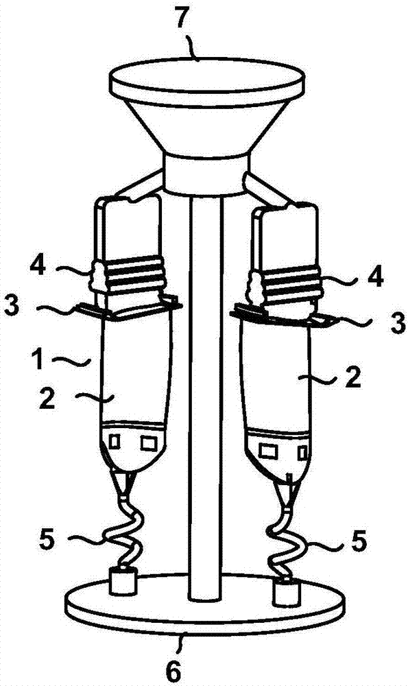
[0045] A certain type of hollow turbine blade casting system model 1 includes a module with two blades, which are distributed axisymmetrically. Among them, the main geometric parameters of the blade are blade body length 101mm, maximum chord length 59.21mm, maximum inscribed circle radius 5.67mm, and trailing edge radius 1.27mm. The blade includes a blade profile 2, a rafter plate 3, and a tenon 4 that meet aerodynamic requirements. According to the casting feeding theory and actual production experience, in order to ensure the stability of the alloy, the pouring method is adopted from the pouring riser 7 with the tenon 4 downward, and the cold copper 6 is quenched to form directional solidification, and the spiral type is adopted according to the actual pouring situation of the factory. Crystal selector 5, the pouring system can re...


PUM


Abstract

The invention discloses a determining method of designed shrinkage of a hollow turbine blade investment casting mold, and relates to hollow turbine blade investment casting molds. The method is particularly applicable to designing of a mold cavity of a hollow turbine blade investment profile mold. A deformation model of hollow blades is obtained through a finite element method, by cutting out a series of two-dimension cross sections on a blade deformation model and a design model, and making a section line discretized into points, distances among the corresponding points are obtained to builda two-dimension displacement site; bending and torsion deformation and shrinkage deformation included in the displacement site are separated. The inner cross section and the outer cross section of theblades are subjected to line connection processing, afterwards blade stopping structures and non-stopping structures are recognized, then the wall thickness of the hollow blades is calculated, and bycalculating shrinkage of different structures, the distribution of the nonlinear shrinkage is built. Finally a shrinkage model is subjected to least square fit of cubic polynomial, and the determination of the designed shrinkage of the investment casting mold is achieved. The finished product rates of the turbine blades are greatly increased, the cycle for mold testing is shortened, and the frequency for mold testing is reduced. The determining method has the advantages of being short in design cycle, high in precision and high in efficiency.

Description

technical field [0001] The invention relates to a precision casting mold for a hollow turbine blade, in particular to a method for determining the design shrinkage rate of a precision casting mold for a hollow turbine blade. Background technique [0002] Hollow turbine blades are the most critical hot-end components of high-performance aeroengines. It is usually manufactured by investment casting process, and its precision casting mold, especially the design and manufacturing quality of the cavity directly affects the forming accuracy and quality of the turbine blade. In order to ensure the size and shape accuracy of the part forming, the cavity design of the mold must consider the compensation for the shrinkage deformation of the blade. [0003] Through years of development, Western countries such as the United States and the United Kingdom have mastered the manufacturing technology of high-performance film-cooled hollow turbine blades, such as Rolls-Royce (RR), Pratt & Wh...

Claims


Application Information

Patent Timeline
IPC IPC(8): G06F17/50
Inventor 董一巍李效基赵奇王尔泰尤延铖
Owner XIAMEN UNIV
Why Eureka
Try Eureka