Eureka AIR delivers breakthrough ideas for toughest innovation challenges, trusted by R&D personnel around the world.

Planar inertial measurement units based on gyros and accelerometers with a common structure

a technology of inertial measurement and common structure, applied in the direction of instruments, navigation instruments, turn-sensitive devices, etc., can solve the problems of high fabrication yield without which integration is not possible, and achieve the effect of simplifying imu design, reducing fabrication process requirements, and improving yield

Inactive Publication Date: 2005-02-22
MILLIE SENSOR SYST & ACTUATORS
View PDF3 Cites 81 Cited by
  • Summary
  • Abstract
  • Description
  • Claims
  • Application Information

AI Technical Summary

Benefits of technology

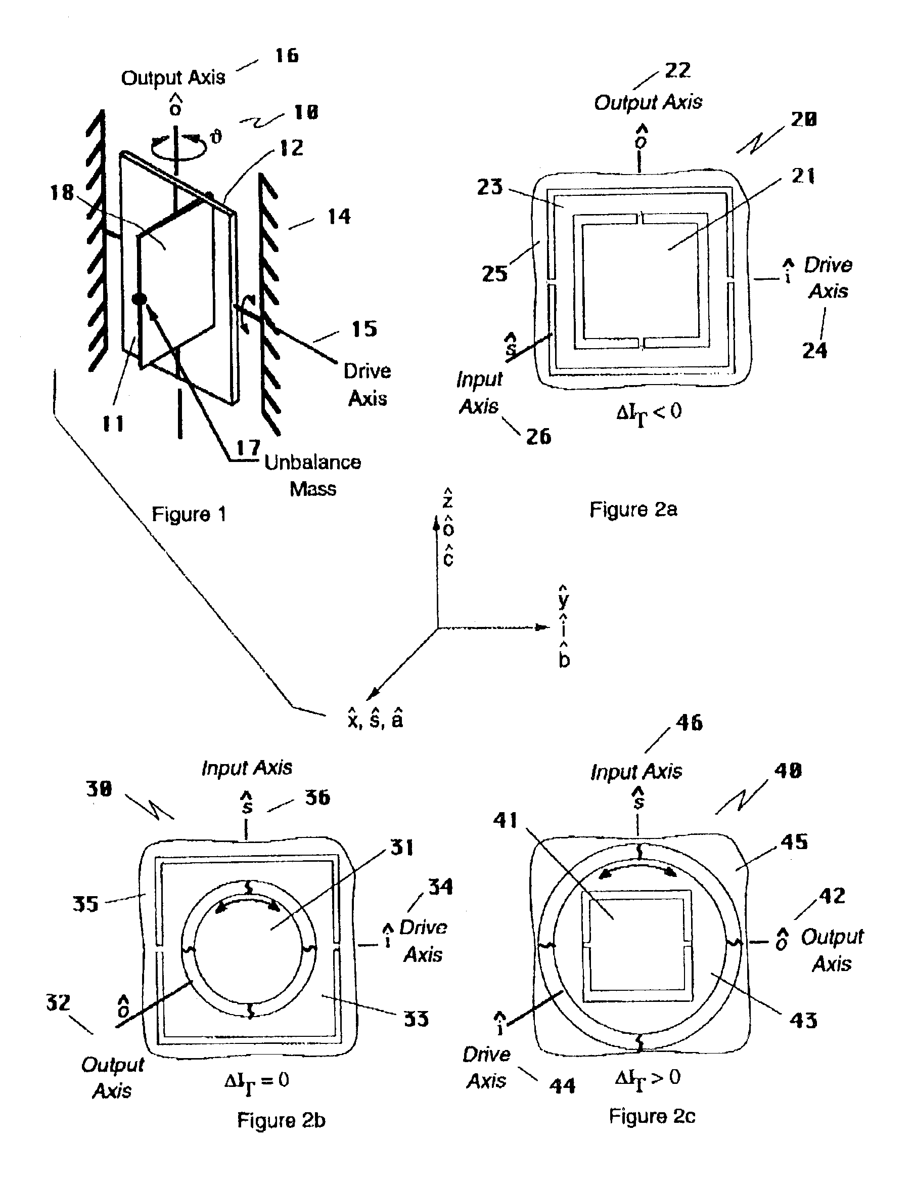
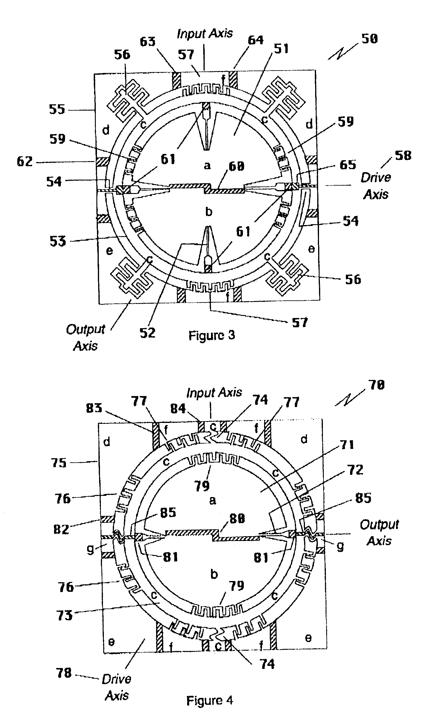
This invention relates to the design and fabrication of integrated, planar inertial measurement units (IMUs) based on planar gyroscopes and accelerometers having a common structure. The common structure is the key to a simpler structural design that is easier to build resulting in high fabrication yield without which integration is not possible. The common structure also simplifies the functional design resulting in improved performance. MEMS integration benefits performance because it prevents tolerance build-up that occurs with the assembly of separate parts to form the whole. With the absence of tolerance build-up, errors due to uncertainty are reduced and instrument stability improved.
Generally an Inertial Measurement Unit (IMU) can contain any number of gyroscopes and accelerometers. The typical IMU is a six degree-of-freedom (DOF) design containing three single DOF gyroscopes and three single DOF accelerometers. However some applications do not require the measurement of six degrees of freedom and therefore a lower number of instruments will suffice. It is also true in the case of the six DOF IMU, that more than three gyroscopes and three accelerometers can be used. That is because integration allows more sophisticated designs to be configured whereby additional instruments are added to build-in redundancy or to differentially (with pairs of instruments) remove common mode errors, etc. Various combinations of gyroscopes and accelerometers will occur to those skilled in the art of IMU design.
Consideration1—MEMS integration is essential to achieving the best performance in a miniature IMU.Consideration2—MEMS gyroscopes and accelerometers based on a common structure reduce the requirements on fabrication processes thereby improving yield without which an Integrated IMU is not possible.Consideration3—MEMS gyroscopes and accelerometers based on the common structure simplify the IMU design.Consideration4—Standard gyroscope and accelerometer designs form the basis for designing various IMUs.Consideration5—An integrated IMU makes the most efficient use of space resulting in the smallest size.Consideration6—An integrated IMU requires one package that provides a common environment for all instruments.

Problems solved by technology

The common structure is the key to a simpler structural design that is easier to build resulting in high fabrication yield without which integration is not possible.

Method used


Image

  • Planar inertial measurement units based on gyros and accelerometers with a common structure
  • Planar inertial measurement units based on gyros and accelerometers with a common structure
  • Planar inertial measurement units based on gyros and accelerometers with a common structure

Examples


first embodiment

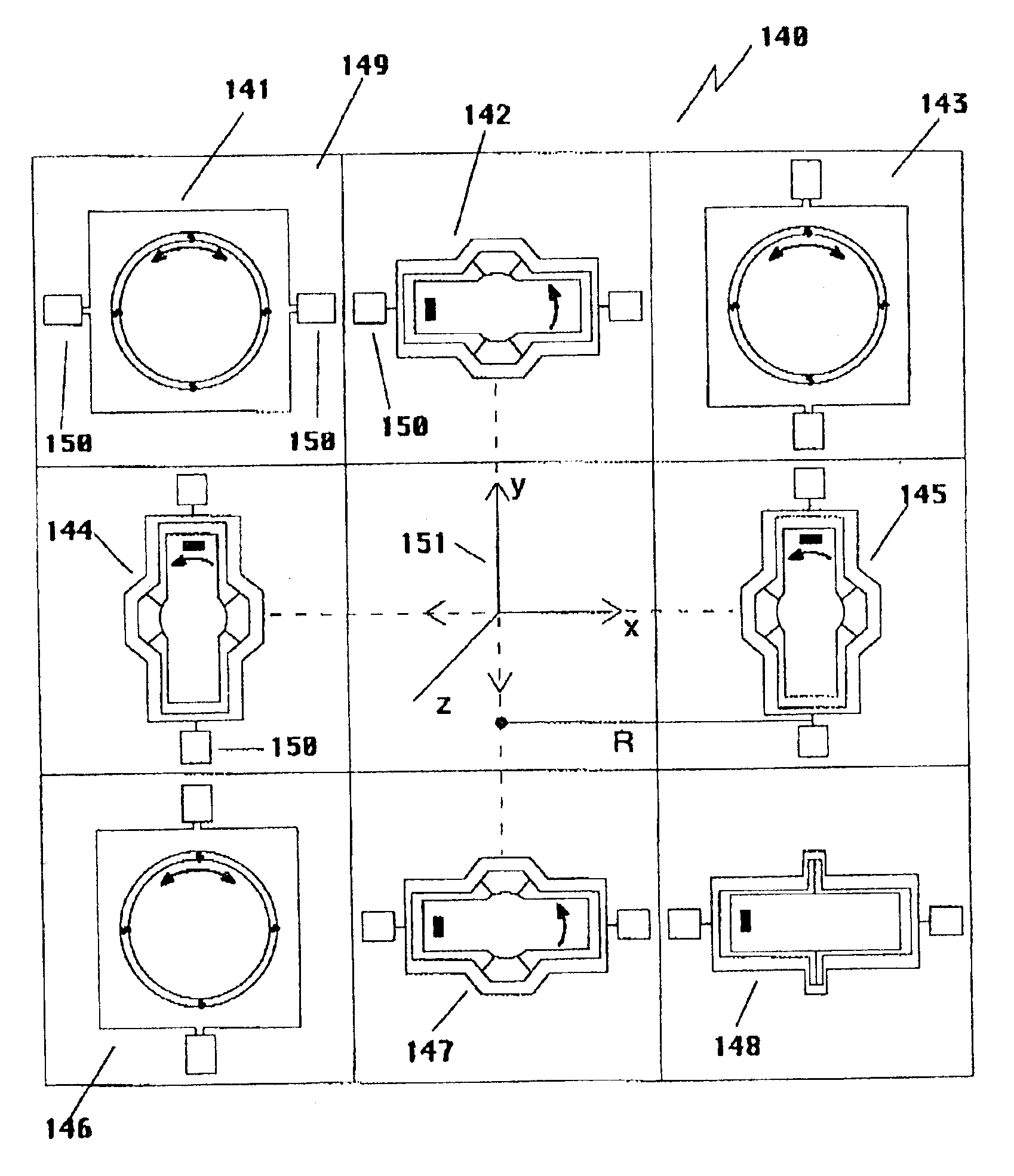
A second benefit of the cross configuration of accelerometers is that the measurement of acceleration along the x-axis and along the y-axis can be done differentially by each set of two accelerometers. Differential operation is a means to cancel non-acceleration, common mode signals. In the first embodiment, the two y-gyroscopes can also be operated differentially.

A first variation on the first embodiment can be obtained by adding a second gyro Gy in the location of accelerometer Az and moving the accelerometer into the center cell position. The result is that all instruments are placed symmetrically about the center of the IMU and all except for the z accelerometer can be operated differentially.

A second variation on the first embodiment is to use any other planar accelerometer design regardless of whether it is dynamically tunable or not.

Second Integrated IMU Based on the Common Structure

A second, six DOF, integrated IMU embodiment is based on gyroscopes of the second configuratio...


PUM


Abstract

Inertial Measurement Units based on integrated designs to reduce alignment and assembly costs. Integration also leads to performance improvement, increased miniaturization and simplification as well as reduced cost. Also disclosed are gyroscopes and accelerometers that are identical, yet by their mechanization, can be made to act as separate sensors. Miniaturization and simplification is improved by combining instruments that can share a common member. Savings in space and complexity are also possible in the electronics when elements are shared.

Description

BACKGROUND OF THE INVENTIONInertial Measurement Units (IMUs) measure the motion of a body in six degrees of freedom using a set of gyroscopes and accelerometers with input axes aligned with three orthogonal axes. The instruments are typically self-contained devices with electronics and a package. Each instrument is tested prior to use in an IMU. The instruments are then assembled with the proper alignment onto a stable member of the system. With expensive high performance IMUs, the cost associated with this approach may be acceptable. However, with miniature, low cost instruments having correspondingly lower performance, the approach is not cost effective. The solution is to make use of integrating technologies such as Microelectromechanical Systems (MEMS) to fabricate all the instruments at the same time on one substrate to produce an IMU in one package. The testing will be done at the IMU level. In addition to cost and size reduction, integration provides benefits that improve per...

Claims


Application Information

Patent Timeline
Patent Type & Authority Patents(United States)
IPC IPC(8): G01C21/10G01P15/18G01C21/16G01C19/56G01C19/5719
CPCG01C19/5719G01P15/18G01C21/16G01C21/166G01C21/183
Inventor CARDARELLI, DONATO
Owner MILLIE SENSOR SYST & ACTUATORS
Why Eureka
Eureka Blog
Learn More