
Preparation method of rolling bearing

A technology for rolling bearings and bearings, which is applied to bearings, bearing components, shafts and bearings, etc. It can solve the problems of non-optimal structure performance, not satisfying the shape of the bearing ring blank, and not being as good as the bearing steel blank, so as to avoid point contact fatigue damage , good comprehensive mechanical properties, the effect of improving hardness and wear resistance

Inactive Publication Date: 2017-12-22
张天贵
View PDF5 Cites 7 Cited by
  • Summary
  • Abstract
  • Description
  • Claims
  • Application Information

AI Technical Summary

Problems solved by technology

[0004] 2. Some bearings are installed in the heart of large equipment, and it is very troublesome to disassemble and assemble the equipment for lubrication;
[0005] 3. Bearings on transportation equipment are difficult to track and maintain after leaving the factory
If the graphite ball is not round and the ball diameter is large, such holes and pits will become the initiation point or crack initiation area of ​​point contact fatigue cracks. The graphite obtained by traditional casting is not in good shape, which is not enough to avoid contact fatigue. the germination point;
[0008] 2. The castings provided by traditional casting methods inevitably contain pores, sand holes, slag inclusions and shrinkage porosity defects, which are far less dense than forged bearing steel blanks;
[0009] 3. The as-cast structure of traditional cast nodular cast iron is relatively coarse, which leads to prolonged quenching holding time and isothermal transformation time during austempering (respectively 1.5 and 2 hours or more), low heat treatment efficiency, increased product cost, and poor microstructure and properties. not optimal;
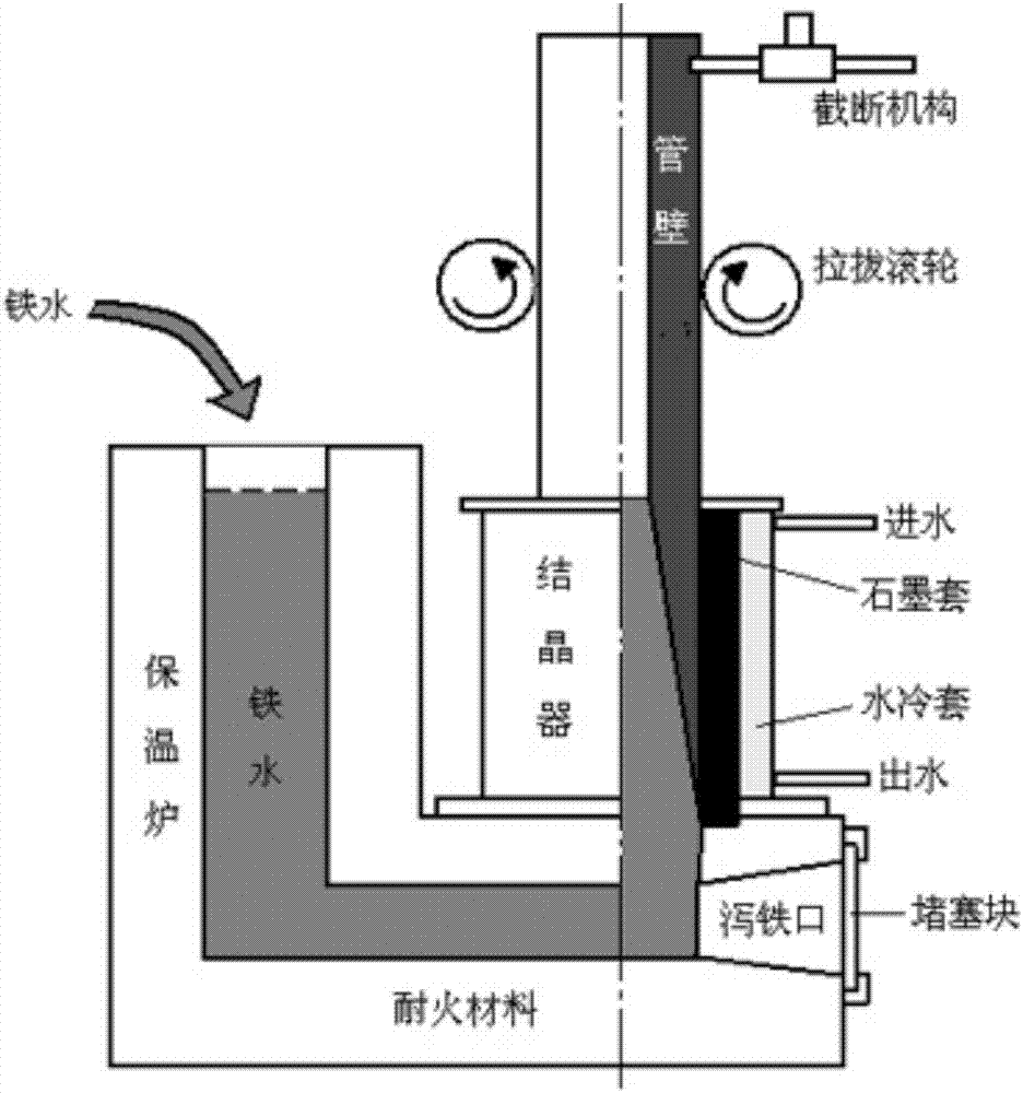
[0010] 4. Although the horizontal continuous casting of cast iron profiles has achieved the finer structure of cast iron materials and even zero defects, it is difficult to draw hollow profiles by this method, which obviously cannot meet the needs of bearing rings for the shape of material blanks
[0011] The existence of the above-mentioned design considerations has hindered people from using ductile iron materials to manufacture self-lubricating rolling bearings, so that no self-lubricating rolling bearings have come out yet.

Method used


Image

  • Preparation method of rolling bearing
  • Preparation method of rolling bearing
  • Preparation method of rolling bearing

Examples


Embodiment Construction

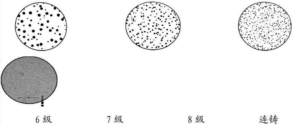
[0040] Attached below Figure 1-6 Embodiments of the present invention are described.

[0041] A material preparation and processing method for a rolling bearing, comprising the steps of:

[0042] 1) Preparation of tube blank material for inner and outer rings of bearings: use medium frequency induction furnace to melt molten iron, the initial composition (%) of molten iron is: C: 3.4-3.7, Si: 1.3-1.7 (adjusted according to the required grade of ductile iron), Mn: 0.2 -0.7, Cr: 0.1-0.3, Cu≤0.8, S≤0.05, P≤0.05, Fe: balance.

[0043] 2) Inoculation and spheroidization treatment: Use ferrosilicon inoculants for ductile iron and nickel-magnesium, nickel-copper spheroidizers to make the final silicon content of molten iron reach 2.3-2.7%, and the residual magnesium content is about 0.04%; try to avoid rare earth during operation And the incorporation of titanium in order to obtain the highest spheroidization rate.

[0044] 3) Preparation of tube blank material for bearing cage: ...


PUM


Abstract

The invention provides a preparation method of a rolling bearing. Inner and outer rings and a retainer of the rolling bearing are made of a nodular cast iron material instead of bearing steel. A new casting method is provided for preparing nodular cast iron pipe blanks for the rolling bearing. Great change is made for material selection, the hot processing technology and hardness of the inner and outer rings and the retainer of the rolling bearing so as to combine the advantages of the rolling bearing and a self-lubricating sliding bearing. The self-lubricating sliding bearing which can operate under the working conditions of low rotational speed, high working temperature, not frequent injection of lubricating grease and frequent impact is provided for the metallurgical machinery and other equipment manufacturing fields.

Description

technical field [0001] The invention belongs to the technical field of bearing preparation, and in particular relates to a method for preparing a rolling bearing. This bearing is suitable for use under the conditions of low speed and high working temperature, but it is difficult to add lubricating grease frequently, and it is frequently impacted. Background technique [0002] The role of the bearing is to reduce the mutual friction between the running shaft and the stationary shaft seat. Therefore, lubricating the bearing to reduce frictional resistance and prolong its life has become the eternal theme of the bearing. People first invented shaft sleeves and sliding bearings, and later invented sliding bearings from lubrication. However, the frictional resistance of sliding friction is large, and it cannot be applied to medium and high-speed rotation conditions. The birth of rolling bearings solved this problem, thus obtaining a wide range of industrial applications and beco...

Claims


Application Information

Patent Timeline
IPC IPC(8): F16C33/66F16C33/62F16C33/44F16C33/56F16C33/64C22C37/10C22C37/04C21D9/40C21D5/00C21D1/20
CPCF16C33/6696C21D1/20C21D5/00C21D9/40C21D2211/001C21D2211/005C22C37/04C22C37/06C22C37/10F16C33/44F16C33/56F16C33/62F16C33/64F16C2204/62F16C2220/02F16C2223/10
Inventor 张天贵
Owner 张天贵
Learn More