
Supercritical electronic injection flash boiler

A flash boiler, supercritical technology, applied in steam generation, steam engine installations, machines/engines, etc., can solve problems such as non-conformance, large boiler size, simple understanding, etc., to increase safety, expand heat exchange area, improve The effect of thermal efficiency

Inactive Publication Date: 2017-11-03
广西汽能壹号节能技术有限公司
View PDF4 Cites 6 Cited by
  • Summary
  • Abstract
  • Description
  • Claims
  • Application Information

AI Technical Summary

Problems solved by technology

[0002] The whole world has been studying how to improve the thermal efficiency of the boiler body to save natural resources. Generally, it is the research on the manufacturing materials and the way of fuel entry, and then gradually produces subcritical, supercritical, and ultra-supercritical. Boiler, but it has not broken through the basic structure of the boiler and the way of steam water supply. Currently, it is still in the state of the traditional heating mode and the steam production mode of boiling bubbles.
[0003] Traditional boilers are bulky and complex in structure, the steam water supply method is backward, the boiler startup and shutdown consumes a lot of energy, the operation is complicated and takes a long time, the selection and application of heat transfer medium is unreasonable, and the understanding of heat energy generation is simple and cannot be applied from various theories to practice. Breaking through the original traditional structure and operation mode, the steam generation process does not conform to the scientific and technological development status of the cross-application of various sciences and the comprehensive application of various principles in modern society; upgrade

Method used


Image

  • Supercritical electronic injection flash boiler
  • Supercritical electronic injection flash boiler

Examples


Embodiment Construction

[0032] The present invention will be further described below in conjunction with the accompanying drawings and specific implementation.

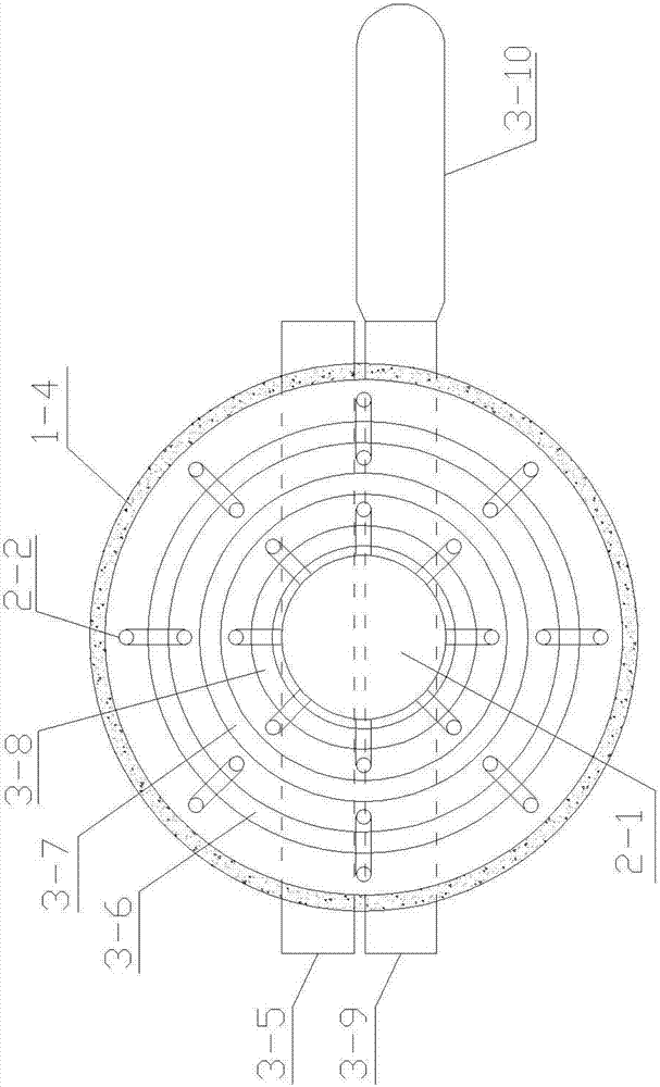
[0033] The structure of the supercritical EFI flash boiler of the present invention is as follows figure 1 , figure 2 As shown, the supercritical EFI flash boiler consists of molten salt feeding pipe 1-1, molten salt tank 1-2, molten salt discharge pipe 1-3, insulation layer 1-4, combustion chamber 2-1, and flue gas pipe 2 -2, flue gas chamber 2-3, burner 2-4, waste heat recovery water tank 3-1, outlet pipe 3-2, high-pressure plunger pump 3-3, high-pressure spray device 3-4, steam generator 3-5 , the first steam coil 3-6, the second steam coil 3-7, the third steam coil 3-8, the steam tank 3-9, the cylinder 3-10, the smoke exhaust pipe 3-11, the water inlet pipe 3 -12. First flue gas tank 3-13, second flue gas tank 3-14, air pipe 3-15, water tank 3-16, steam turbine 4-1, generator 4-2, first electric heater 4- 3 and the second electric he...


PUM


Abstract

The invention discloses a supercritical electronic injection flash boiler. The supercritical electronic injection flash boiler is composed of a fused salt adding pipe, a fused salt groove, a fused salt discharge pipe, an insulating layer, a burning cavity, a smoke pipe, a smoke cavity, a burning machine, a waste heat recovery water tank, a water outlet pipe, a high pressure plunger pump, a high pressure spray mist device, a steam generator, a first steam coiler, a second steam coiler, a third steam coiler, a steam groove, a steam header, a smoke discharge pipe, a water inlet pipe, a first smoke groove, a second smoke groove, an air pipe, a water groove, a turbine, a power generator, a first electric heater and a second electric heater. The supercritical electronic injection flash boiler has the beneficial effects that vapor and mist jetting water feeding is adopted, the heat-exchange surface is enlarged, and the heat efficiency is improved; the temperature difference of entering vapor mist and pipe heat generates gas explosion so as to generate the dynamic effect, gas expansion is increased, superheated steam is directly and quickly generated, steam temperature and pressure are adjustable, and the superheated steam is directly produced; and steam temperature and pressure are adjustable.

Description

technical field [0001] The invention relates to a boiler. Specifically, it is a supercritical EFI flash boiler. Background technique [0002] The whole world has been studying how to improve the thermal efficiency of the boiler body to save natural resources. Generally, it is the research on the manufacturing materials and the way of fuel entry, and then gradually produces subcritical, supercritical, and ultra-supercritical. Boiler, but it has not broken through the basic structure of the boiler and the way of steam water supply. At present, it still stays in the state of the traditional heating mode and the steam production mode of boiling bubbles. [0003] Traditional boilers are bulky and complex in structure, the steam water supply method is backward, the boiler startup and shutdown consumes a lot of energy, the operation is complicated and takes a long time, the selection and application of heat transfer medium is unreasonable, and the understanding of heat energy gene...

Claims


Application Information

Patent Timeline
IPC IPC(8): F22B3/08F01K11/02F01K7/32F01K25/08
CPCF22B3/08F01K7/32F01K11/02F01K25/08
Inventor 赖正平石雄伟甘军农成莫林
Owner 广西汽能壹号节能技术有限公司
Learn More