Mold plasma 3D printing device and 3D printing method

A 3D printing and plasma technology, applied in the direction of improving process efficiency, improving energy efficiency, additive manufacturing, etc., can solve the problems of complex structure, long preparation time for mold making, high mold production cost, etc.

Inactive Publication Date: 2016-06-15
SINOADDITIVE MFG EQUIP CO LTD
View PDF16 Cites 5 Cited by
  • Summary
  • Abstract
  • Description
  • Claims
  • Application Information

AI Technical Summary

Problems solved by technology

The Chinese invention patent application document published on August 27, 2014 with the publication number CN104004966A discloses a casting preparation method for stamping dies. Heat treatment and multi-pass processing are required, the designability of the mold and its performance is poor, and the manufacturing process is cumbersome
The Chinese invention patent application document with the publication number CN104057271A published on September 24, 2014 discloses a powder metallurgy preparation method for cemented carbide tools and molds. Since each mold product corresponds to a pair of molds, the shrinkage of different alloy powders The coefficients are different, and each corresponding mold needs to be designed, resulting in high mold production costs; mold preparation time is long, and the preparation efficiency is low; when powder is filled, under the action of friction, the corners are filled unevenly, resulting in uneven strength , affecting the service life of mold products
In the invention patent "Moulds and methods for making molds and casting methods" published on August 13, 2008 with the publication number CN101242923A, a modular group and method of molds are disclosed. The modular group and Method: When preparing molds, the processing accuracy and matching dimension accuracy of each module are required to be very high, and the fixing strength and precision requirements of each module are also very high, resulting in high mold preparation costs
But at present, there are three main problems in the selective electron beam rapid prototyping technology: first, the electron beam rapid prototyping technology needs a vacuum environment to form the energy source electron beam and avoid the oxidation of metal parts during the forming process
This makes the structure of the electron beam rapid prototyping equipment complex, the size of the molded parts is limited, and the molding equipment is expensive; second, the electron beam rapid prototyping technology requires a powder spreading system or a molding material supply system
This makes the structure of the electron beam rapid prototyping equipment complex, not only the size of the formed parts is limited, but also the forming efficiency is low; third, in order to ensure the mechanical properties of the parts, the electron beam rapid prototyping technology requires spherical metal powder with good fluidity
This makes SLM rapid prototyping equipment expensive to run

Method used


Image

  • Mold plasma 3D printing device and 3D printing method
  • Mold plasma 3D printing device and 3D printing method
  • Mold plasma 3D printing device and 3D printing method

Examples


Embodiment 1

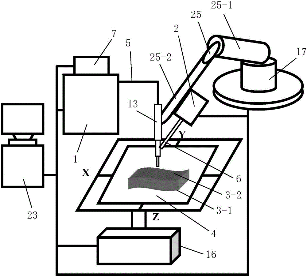
[0087] Such as figure 1 A mold plasma 3D printing equipment shown is composed of a monitoring system, a plasma beam processing system, a horizontal printing table 4 for placing the mold to be formed, and a temporary fixing for temporarily fixing the mold base 3-1 of the mold to be formed. The mold to be formed includes a mold base 3-1 and a molding surface working layer 3-2 arranged on the mold base 3-1; the temporary fixing member is arranged on the horizontal printing table 4.

[0088]The plasma beam processing system consists of a plasma generator equipped with a shower head and used to generate a plasma beam, a gas supply device 1 for supplying working gas to the plasma generator, and a gas supply device 1 for continuously generating plasma beams to the plasma generator. It consists of a powder feeding device for sending printing materials into the plasma beam and a printing position adjustment device for adjusting the printing position. Both the plasma generator and the p...

Embodiment 2

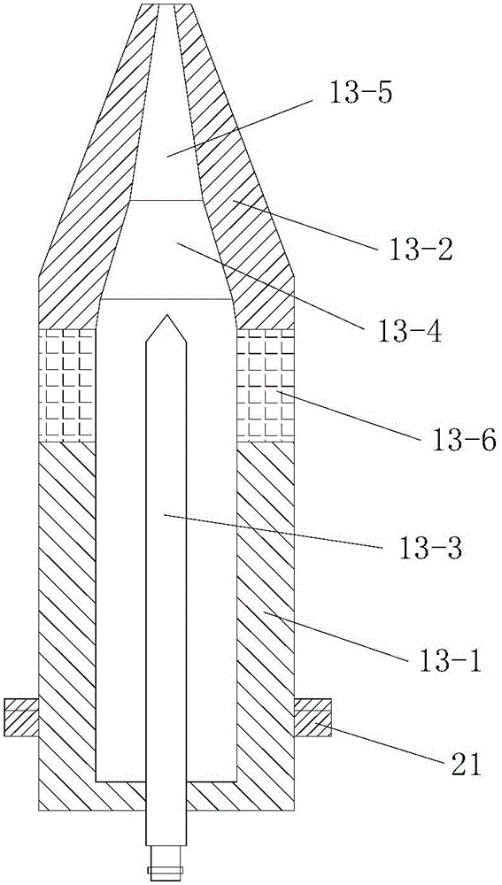
[0200] In this example, if Figure 7 As shown, the mold plasma 3D printing equipment used is different from Embodiment 1 in that: the angle between the nozzle 13-5 and the central axis of the gun body 13-1 is 30°-45°.

[0201] In this way, after changing the direction of the plasma beam through the nozzle 13-5, the thermal load impact of the plasma jet on the anode nozzle 13-2 can be effectively reduced, and the anode ablation condition is improved.

[0202] In this embodiment, the structure, connection relationship and working principle of the remaining parts of the mold plasma 3D printing equipment are the same as those in Embodiment 1.

[0203] In this embodiment, the mold plasma 3D printing method adopted is the same as that in Embodiment 1.


PUM

PropertyMeasurementUnit
Heightaaaaaaaaaa
Layer thicknessaaaaaaaaaa

Abstract

The invention discloses a mold plasma 3D printing device and 3D printing method. The device is composed of a monitor system, a plasma beam machining system, a horizontal printing table for containing a mold to be formed and a temporary fixed piece. The plasma beam machining system is composed of a plasma generator, an air supply device, a powder feeding device and a printing position adjustment device. The printing position adjustment device comprises a horizontal movement device and a printing distance adjustment device. The monitor system comprises a horizontal movement controller, a temperature detection unit, a distance detection unit and a printing distance adjustment controller, and a temperature adjustment and control device is formed by the temperature detection unit and the printing distance adjustment controller. The method comprises the steps that firstly, a three-dimensional model is obtained, and layering slicing treatment is carried out; secondly, a scanning path is filled; thirdly, a printing path is obtained; and fourthly, printing is carried out layer by layer from bottom to top. The device is reasonable in design, easy and convenient to operate, high in efficiency and good in use effect, the forming process is directly carried out in the atmospheric environment, and a formed mold is good in quality.

Description

technical field [0001] The invention belongs to the technical field of rapid prototyping, and in particular relates to a mold plasma 3D printing device and a 3D printing method. Background technique [0002] Mold refers to various molds and tools used in industrial production for injection molding, blow molding, extrusion, die-casting or forging forming, smelting, stamping and other methods to obtain the required products. In short, a mold is a tool used to shape a product. Mold is an important tool in product molding and processing, and the cost accounts for 10% to 30% of product cost. The molding surface of the mold refers to the surface used to shape the product (also called the product), and the molding surface is the surface that directly contacts the molded product. Wherein, the molding surface of the cavity refers to the outer surface for molding the product, and the molding surface of the core is the inner surface for molding the product. The processing quality, p...

Claims


Application Information

Patent Timeline
IPC IPC(8): B22F3/105B33Y10/00B33Y30/00
CPCB33Y10/00B33Y30/00B22F10/00B22F10/22B22F10/322B22F12/90B22F12/41B22F10/30B22F12/53Y02P10/25
Inventor 华云峰程国君郝勇魏志宇
Owner SINOADDITIVE MFG EQUIP CO LTD
Why Eureka
Try Eureka