
Continuous and direct compression molding forming method for thermoplastic plastic thin-wall melt

A thin-walled plastic compression molding technology, applied in the field of plastic molding processing, can solve problems such as low efficiency, limitation of compression molding processing, complex mold manufacturing, etc., and achieve simple production process, easy flow and stretching, and complex equipment and molds Effect

Inactive Publication Date: 2016-01-06
陈元文
View PDF5 Cites 1 Cited by
  • Summary
  • Abstract
  • Description
  • Claims
  • Application Information

AI Technical Summary

Problems solved by technology

The disadvantages of compression molding are that the mold manufacturing is complicated, the investment is large, the production and processing time is long, the efficiency is low, and it is limited by the press. The compression molding process is suitable for mass production of small and medium-sized composite products
[0010] For thin-walled and complex-shaped products, compression molding processing is greatly restricted
First of all, most of the materials used in compression molding are thermosetting plastics. Thermosetting plastic products are hard and brittle, lacking toughness, especially in thin-walled structural designs, and they will break when they are slightly impacted.
Secondly, during the compression molding process, the plastic mixture has almost no molten flow in the mold cavity, and the thin-walled and narrow mold cavity is often unable to be filled, and complex shapes cannot be formed.

Method used


Image

  • Continuous and direct compression molding forming method for thermoplastic plastic thin-wall melt
  • Continuous and direct compression molding forming method for thermoplastic plastic thin-wall melt

Examples


Embodiment Construction

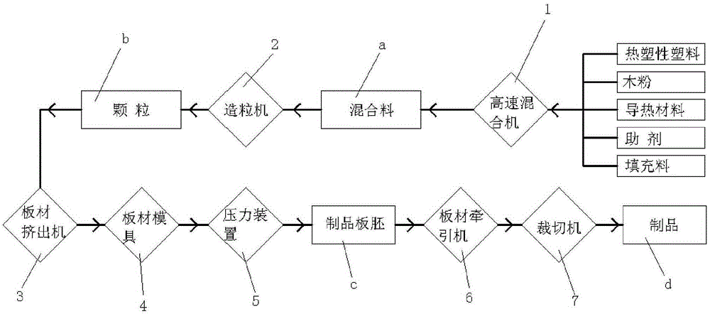
[0031] Attached below Figure 1-2 and specific examples to further illustrate the present invention, but not as a limitation to the present invention.

[0032] In the product of the present invention, its material is a composite material made of the following components in percentage by weight, thermoplastic 50% polyvinyl chloride resin, wood flour 15%, thermal conductive material 10%, filler 15% and auxiliary agent 10%, wherein Thermoplastics include one or more of polyethylene, polypropylene, polyvinyl chloride, ABS, polystyrene polyester, polycarbonate, nylon, etc. Resin powder with a density of 700. The wood powder is pure wood powder with a coupling treatment of more than 100 meshes. The thermal conductive material includes aluminum powder, iron powder, copper powder and other metal monomers or aluminum oxide, magnesium oxide, silicon nitride, nitrogen, etc. Metal or non-metal chemical compounds such as boron oxide, 400-mesh alumina is used as the heat-conducting materia...


PUM


Abstract

The invention discloses a continuous and direct compression molding forming method for thermoplastic plastic thin-wall melt. The method comprises the following continuously and circularly executed steps that firstly, by weight, 50% of thermoplastic plastic, 15% of wood powder, 15% of filler, 10% of heat conduction material and 10% of assistant are placed into a high-speed mixer to be manufactured into a mixture; secondly, the mixture obtained in the first step is placed in a granulator to be manufactured into particles; thirdly, the particles obtained in the second step are placed into a plate extruder, and the melt is formed through heat conduction and shearing; fourthly, the melt obtained in the third step passes a plate mold, and a melt plate blank is formed; fifthly, the melt plate blank obtained in the fourth step is pressed through a mold on a pressure device and manufactured into a product plate blank; and sixthly, the product plate blank obtained in the fifth step is dragged through a plate dragging machine to a cropping machine to be cropped and then separated, and a finished product is obtained. Continuous and circular direct compression molding forming of the thin-wall and wide melt in the molten state is achieved, and the product is high in surface hardness, accurate in size, full in shape and clear in corner angle. The production technology process is simple, the production period is short, and the production efficiency is high.

Description

technical field [0001] The invention relates to a method for molding plastics, and specifically provides a method for continuous direct molding of thermoplastic thin-wall melts. Background technique [0002] Thin-walled plastic products are widely used in packaging, decoration, lighting, advertising, containers and other fields, covering all aspects of our life, work and home. Thin-walled plastic products, like traditional plastic products, can be divided into thin-walled thermoplastic products and thin-walled thermosetting plastic products in terms of the raw materials used. However, the processing and production of thin-walled plastic products is affected by materials, equipment, and technology. Not all existing plastic processing and production methods are suitable for the production of thin-walled plastic products. Currently, there are processing methods that can realize the production of thin-walled plastic products. There are several methods such as injection molding,...

Claims


Application Information

Patent Timeline
Patent Type & Authority Applications(China)
IPC IPC(8): B29C47/00
CPCB29C48/0011
Inventor 陈元文
Owner 陈元文
Learn More