Floating oil collecting device, manufacturing method thereof and applications thereof
A technology for collecting equipment and oil slicks, applied in chemical instruments and methods, other chemical processes, general water supply conservation, etc., can solve the problems of ignoring the volume of oil-absorbing materials, difficulty in large-scale preparation, complex mechanical equipment, etc., and achieve low preparation costs , save manpower and time, and solve the effect of difficult transportation
- Summary
- Abstract
- Description
- Claims
- Application Information
AI Technical Summary
Problems solved by technology
Method used
Image

Examples
preparation example Construction
[0028] The invention provides a preparation method of the floating oil collection device, comprising the following steps:
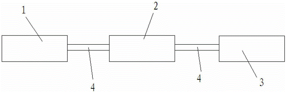
[0029] a) preparing lipophilic and hydrophobic porous material 1;
[0030] b) Insert one end of a tube 4 into the porous material 1 obtained in step a), connect the other end of the tube 4 to the inlet of the pump body 2, and then connect the outlet of the pump body 2 to another The pipe body 4 is connected to the collection container 3 to obtain the floating oil collection equipment.
[0031]In step a), methods well known in the art can be used to prepare lipophilic and hydrophobic porous materials. The present invention first prepares the porous material capable of selectively absorbing oil from the oil-water mixture. The main part of the porous material can be polyester sponge, melamine sponge, cotton, sawdust, paper, straw powder, cotton wool, woven cloth, chemical fiber, polypropylene fiber , one or more of porous polymer membranes. By wrapping a ...
Embodiment 1
[0039] Cut the melamine sponge into a cube with a side length of 4 cm, and immerse the sponge sample in the hydrophobic fumed silica, polydimethylsiloxane prepolymer and n-hexane dispersion, and wait until the sponge sample is completely absorbed by the above-mentioned The dispersion was taken out, dried at room temperature, and solidified at 200° C. for 2 hours to obtain a hydrophobic and lipophilic porous material.
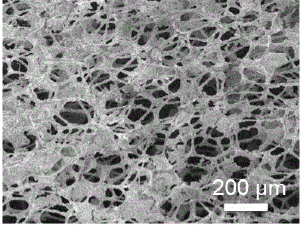
[0040] The above-mentioned hydrophobic and lipophilic porous materials were observed with a field emission scanning electron microscope, and the results can be found in figure 2 ,Depend on figure 2 It can be seen that the hydrophobic and lipophilic porous material used in the present invention has a pore diameter between 50 and 200 μm, and a porosity of about 80%. The contact angle test of the above hydrophobic and lipophilic porous material shows that the contact angle between the surface of the hydrophobic and lipophilic porous material used in the present ...
Embodiment 2
[0043] Take a piece of ordinary cotton cloth (20cm×20cm), spray the polyurethane solution (n-hexane solution of polyurethane prepolymer and its curing agent) on the surface of the cotton cloth by spraying, then dry it in the air, and then heat and cure it at 80 degrees for 12 hours , to obtain a hydrophobic cotton cloth. The above-mentioned hydrophobic cotton cloth is tested for contact angle, and the contact angle between its surface and water droplet is about 150°, which has super-hydrophobic properties.
[0044] Cut the above-mentioned hydrophobic cotton cloth into small pieces, process it into a capsule and fill it with cotton (about 4 grams) (similar to a pillow) to obtain a volume of about 64cm 3 Porous material with a porosity of about 70%.
[0045] Take a polytetrafluoroethylene pipe (inner diameter 3mm, outer diameter 4mm), insert one end into the inner middle part of the porous material, and connect the other end to the inlet of the self-priming pump (rated power 12...
PUM
| Property | Measurement | Unit |
|---|---|---|
| pore size | aaaaa | aaaaa |
| voidage | aaaaa | aaaaa |
| voidage | aaaaa | aaaaa |
Abstract
Description
Claims
Application Information
 - R&D
- Intellectual Property
- Life Sciences
- Materials
- Tech Scout
- Unparalleled Data Quality
- Higher Quality Content
- 60% Fewer Hallucinations
Browse by: Latest US Patents, China's latest patents, Technical Efficacy Thesaurus, Application Domain, Technology Topic, Popular Technical Reports.
© 2025 PatSnap. All rights reserved.Legal|Privacy policy|Modern Slavery Act Transparency Statement|Sitemap|About US| Contact US: help@patsnap.com