
Two-Dimensional Position Sensor

a position sensor and two-dimensional technology, applied in the direction of instruments, cathode-ray tube indicators, electric digital data processing, etc., can solve the problems of high production cost, high mounting cost, and direct exposure of the sensing layer to abuse and easily damaged

Active Publication Date: 2007-01-11
NEODRON LTD
View PDF8 Cites 345 Cited by
  • Summary
  • Abstract
  • Description
  • Claims
  • Application Information

AI Technical Summary

Benefits of technology

[0011] Because the position sensor is based on sensing electrodes on only a single surface, it can be cheaper to manufacture than known double-sided position sensors. This also means the sensing electrodes can be deposited directly onto a surface for which the opposing surface is inaccessible (e.g. a display screen). The sensing electrodes can also be deposited on an inside surface of a device housing, thus removing the need for any protective covering that might be required if electrodes were also required to be on the outer surface.
[0023] The processor may be operable to compensate for position distortion introduced by the physical geometry of the patterned conductive material.

Problems solved by technology

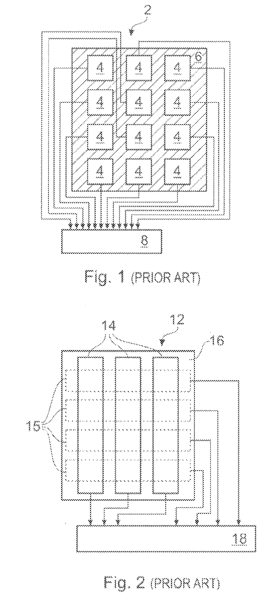
A significant disadvantage of these types is that there has to be an opening in the panel, which requires sealing against moisture and dirt and hence is expensive to mount.
Furthermore the sensing layer is directly exposed to abuse and can be easily damaged by sharp objects or abrasion.
Furthermore these screens are very expensive to produce and in fact cannot be produced on a mass scale; additionally the sensing circuitry is known to be complex and expensive.
However these types only provide for limited resolution, as predefined by the location of discrete electrode shapes.
While it is well known that these electrodes can be made of a single layer of clear conductor such as Indium Tin Oxide (‘ITO’) to allow placement over a bezel-less display, for example by the application of the layer as a film on the back of a subsection of a panel, nevertheless the technology is limited to discrete touch areas based on the number, size, and placement of discrete electrodes.
However U.S. Pat. No. 5,463,388 fails to show how to implement such a design and describes instead a matrix of conductors along with a centroidal calculation of continuous X-Y position.
In fact it is not practical to have so many sensing channels as one per sense pad, and a matrix arrangement is much more efficient as described below.
However this type requires two sensing layers so that the matrix traces can be routed, and does not allow the use of optically clear materials.
This set of ideal goals has not been achieved with any known prior art.

Method used


Image

  • Two-Dimensional Position Sensor
  • Two-Dimensional Position Sensor
  • Two-Dimensional Position Sensor

Examples


Embodiment Construction

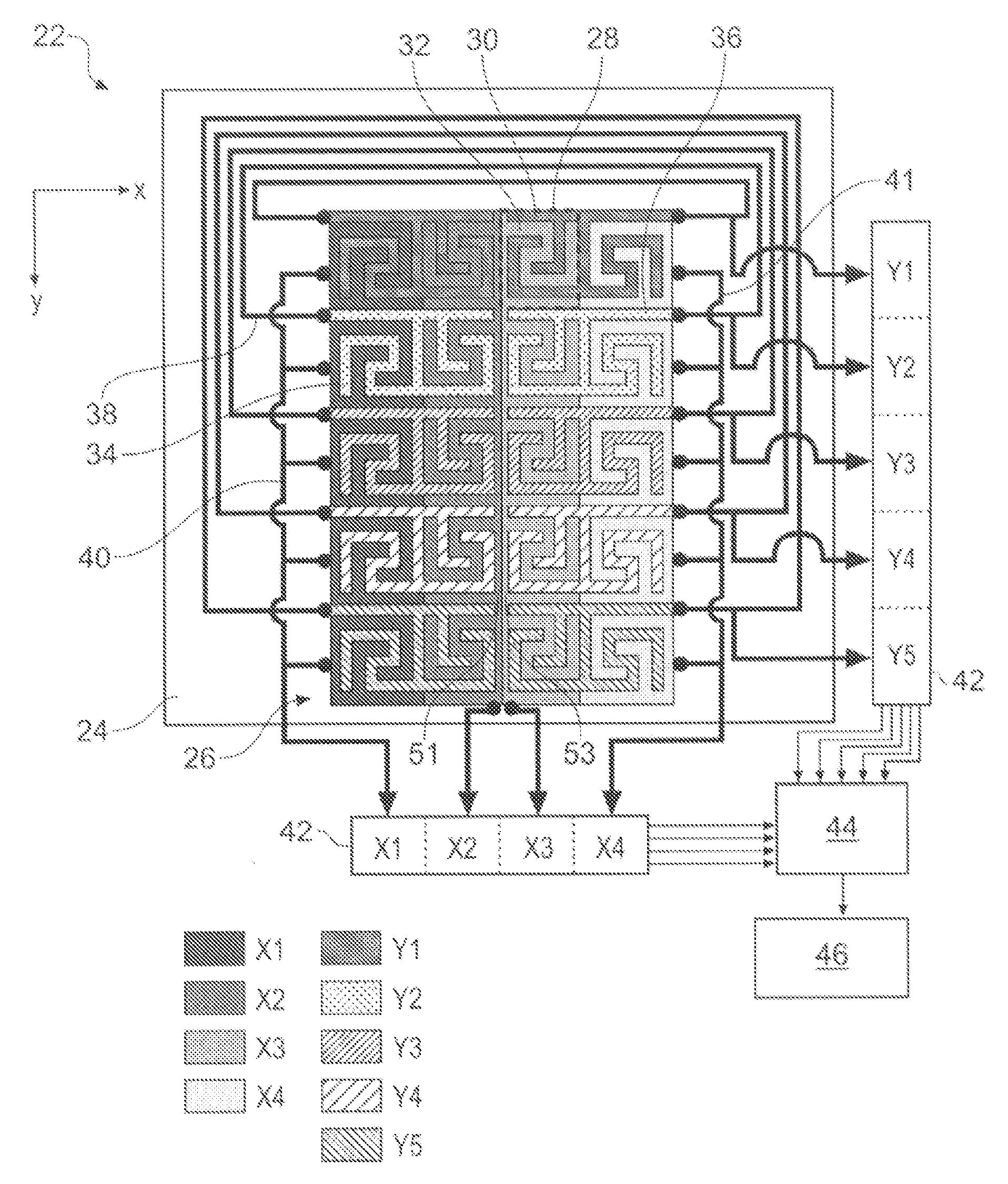
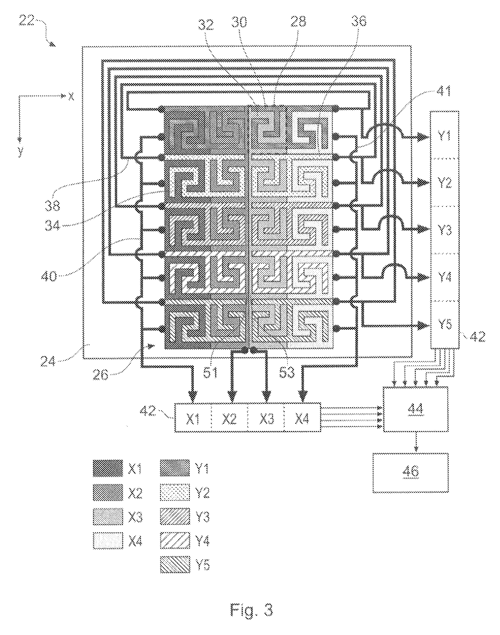
[0036]FIG. 3 schematically shows in plan view a two-dimensional touch-sensitive capacitive position sensor 22 according to an embodiment of the invention. The position sensor 22 is operable to determine the position of an object along a first (x) and a second (y) direction, the orientation of which are shown towards the top left of the drawing. The sensor 22 comprises a substrate 24 having an arrangement of sensing electrodes 26 mounted thereon. The sensing electrodes 26 define a sensing area within which the position of an object (e.g. a finger or stylus) adjacent the sensor may be determined. The substrate 24 is of a transparent plastics material and the electrodes are formed from a transparent film of Indium Tin Oxide (ITO) deposited on the substrate 24 using conventional techniques. Thus the sensing area of the sensor is transparent and can be placed over a display screen without obscuring what is displayed behind the sensing area. In other examples the position sensor may not b...


PUM


Abstract

A capacitive position sensor for determining the position of an object along first and second directions is described. The sensor comprises a substrate having an arrangement of electrodes mounted on a single surface thereof. The electrodes are arranged so as to define an array of sensing cells arranged in columns and rows to form a sensing area. Each of the sensing cell including a column sensing electrode and a row sensing electrode with the column sensing electrodes of sensing cells in the same column being electrically coupled together and the row sensing electrodes of sensing cells in the same row also being electrically coupled together. Row sensing electrodes of sensing cells at opposing ends of at least one of the rows are connected together by an electrical connection made outside of the sensing area so that there is no requirement for electrical connections to cross within the sensing area, thus providing a capacitive position sensor having a sensing area with electrodes on only one side of a substrate.

Description

BACKGROUND OF THE INVENTION [0001] The invention relates to a capacitive position sensor for determining the position of an object within a two-dimensional sensing area. [0002] The use of two-dimensional touch-sensitive position sensors is becoming more common. Examples include the use of position sensors in laptop computers in place of mouse pointing devices, as control panels for receiving user inputs to control an appliance, or particularly as a glass touchscreen apparatus having an X-Y coordinate output. Some applications require a clear sensing layer so that a display can be viewed beneath the screen, while others only require an opaque touch surface, for example for a keypanel on a kitchen appliance or a PC peripheral. [0003] Touch-sensitive position sensors are frequently preferred to mechanical devices because they provide for a more robust interface and are often considered to be more aesthetically pleasing. Furthermore, because touch-sensitive position sensors require no m...

Claims


Application Information

Patent Timeline
IPC IPC(8): G09G5/00G06F3/041
CPCG06F3/0416G06F3/0418G06F3/044H01L2924/0002H01L2924/00G06F3/04186G06F3/0443G06F3/04164G06F3/0448H03K17/9622G06F3/0446G06F3/0412
Inventor HRISTOV, LUBEN
Owner NEODRON LTD
Learn More