


Quick Research
Generate reliable direction feasibility study reports for your R&D in just a few steps.

Technical Q&A
Discover and master advanced knowledge NOW. Basics, ideas, possibilities, all at once.

Find Solutions
As an expert in R&D theories, this can generate solutions to your technical problems instantly.

Evaluate Feasibility
Analyze your overall solution with one click, know your potential R&D risks in advance.

Monitor Landscape
Get weekly tech updates, stay abreast of the latest tech innovations and key insights.
Dressing and manufacture of outer blade cutting wheel
A technology of cutting wheels and outer blades, which is applied in the direction of manufacturing tools, bonded grinding wheels, and grinding machine parts, etc., can solve problems affecting cutting performance, cutting accuracy errors, etc., and achieve efficient and satisfactory dressing results
- Summary
- Abstract
- Description
- Claims
- Application Information
AI Technical Summary
Problems solved by technology
Method used
Image

Examples
example 1
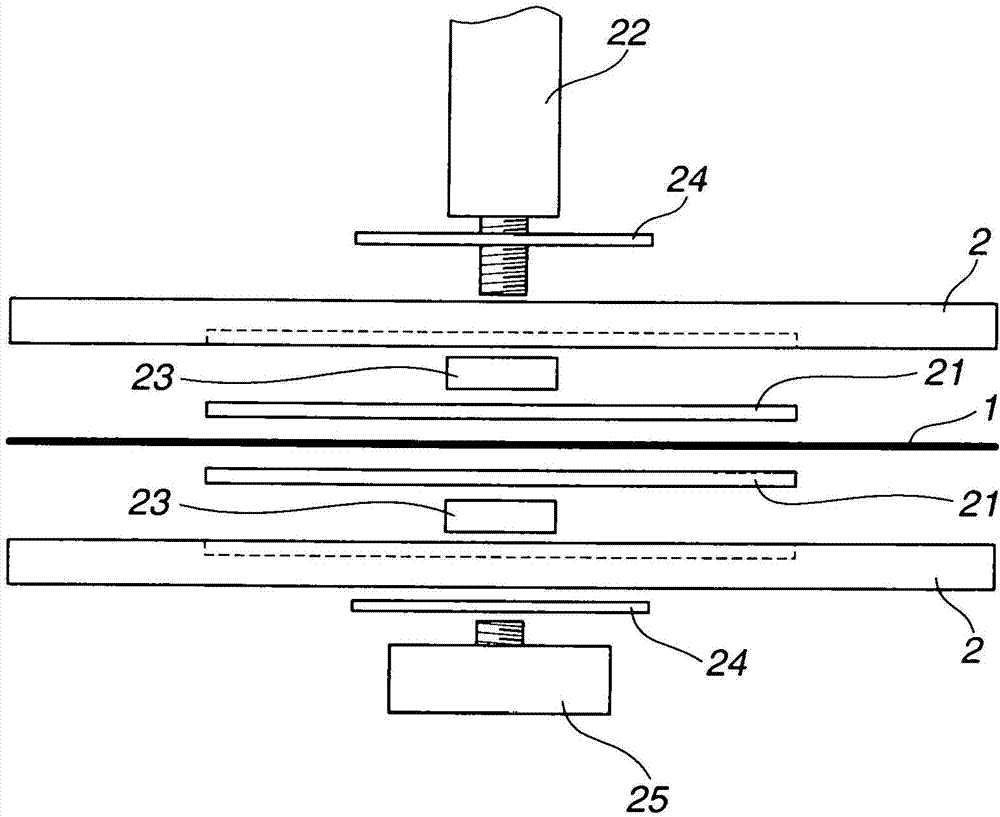
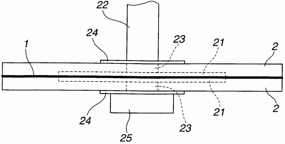
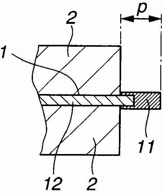
[0075] A cemented carbide substrate in the form of an annular thin disk held by clamping it between a pair of circular clamps, as figure 1 , 2A and 2B, the annular thin disc has an inner diameter of 60 mm and an outer diameter of 133 mm. The circular clamp had an outer diameter 2 mm smaller than that of the base so that the outer edge of the base protruded 1 mm beyond the outer circumference of the clamp. Electroplating was performed in Nickel Bath #1 as defined below to deposit the undercoat. The substrate is then held by clamping it between a pair of circular clamps 2, 2, as figure 1 , 2A and 2C. The circular clamps 2, 2 have an outer diameter 2 mm larger than that of the base body. Permanent magnet segments are built into the outer peripheral portion of the jig. The space defined between the outer peripheral portions of each clamp ( Figure 2C ) was filled with 0.8 g of diamond abrasive particles pre-coated with magnetic material (nickel) and having an average partic...
example 2
[0117] Outer blade cutting wheels were fabricated as in Example 1, except that layer plating was omitted and instead a Sn-Pb alloy was infiltrated into the abrasive layer or blade portion. The infiltration of the Sn-Pb alloy is carried out by the following process: the substrate carrying the blade part is placed on a heating plate at 230° C.; the substrate is heated for 5 minutes; using a soldering iron at 230° C. A wire of the alloy is melted; the molten alloy is applied to the hot blade portion on the substrate; the alloy is allowed to infiltrate; and the blade portion is allowed to cool down.
[0118] Using the outer blade cutting wheel, under the same conditions as in Example 1, the rare earth permanent magnet block (Nd-Fe-B magnet) was cut and processed into magnet pieces. Figure 9B is a photograph showing the cut surface of the cut magnet piece. Depend on Figure 9B It is evident that the cut surface is smooth and there are no cut marks. Using the outer blade cutting...
PUM
| Property | Measurement | Unit |
|---|---|---|
| diameter | aaaaa | aaaaa |
| particle size | aaaaa | aaaaa |
| diameter | aaaaa | aaaaa |
Abstract
Description
Claims
Application Information
 - R&D Engineer
- R&D Manager
- IP Professional
- Industry Leading Data Capabilities
- Powerful AI technology
- Patent DNA Extraction
Browse by: Latest US Patents, China's latest patents, Technical Efficacy Thesaurus, Application Domain, Technology Topic, Popular Technical Reports.
© 2024 PatSnap. All rights reserved.Legal|Privacy policy|Modern Slavery Act Transparency Statement|Sitemap|About US| Contact US: help@patsnap.com