
Flue gas desulfurization process for comprehensively utilizing sintering flue gas

A technology of sintering flue gas and desulfurization process, which is applied to the improvement of process efficiency, waste heat treatment, lighting and heating equipment, etc. It can solve the problems of adverse impact on the atmospheric environment, waste of resources and energy, increased costs and burdens, and achieve the protection of the atmosphere Environmental quality, saving energy and resources, beneficial to the effect of dilution and diffusion

Active Publication Date: 2009-11-04
ZHONGYE-CHANGTIAN INT ENG CO LTD
View PDF3 Cites 9 Cited by
  • Summary
  • Abstract
  • Description
  • Claims
  • Application Information

AI Technical Summary

Problems solved by technology

[0009] It can be seen from the above that the waste heat recovery of the existing annular cooler is mainly to recycle the hot exhaust gas in the middle temperature zone and (sub)high temperature zone of the annular cooler, but the low temperature District heat waste gas is not recycled but directly discharged into the atmosphere, which wastes resources and energy and has adverse effects on the atmospheric environment
In addition, because the temperature of the sintering flue gas entering the water washing tower is high, the water washing tower requires a large amount of cooling water and a long cooling time, which also wastes resources and energy and increases the cost and burden of the enterprise

Method used


Image

  • Flue gas desulfurization process for comprehensively utilizing sintering flue gas
  • Flue gas desulfurization process for comprehensively utilizing sintering flue gas
  • Flue gas desulfurization process for comprehensively utilizing sintering flue gas

Examples


Embodiment

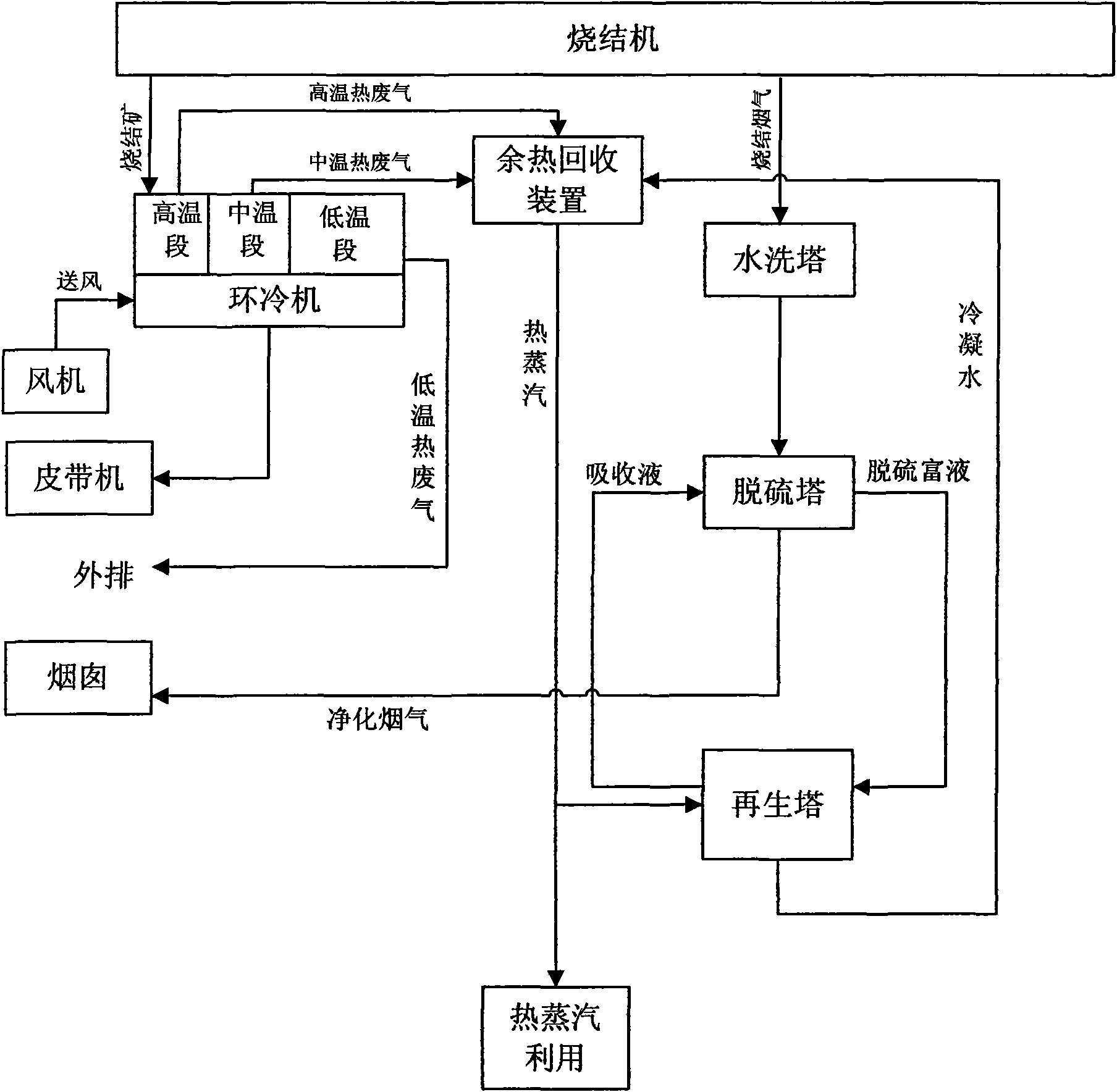
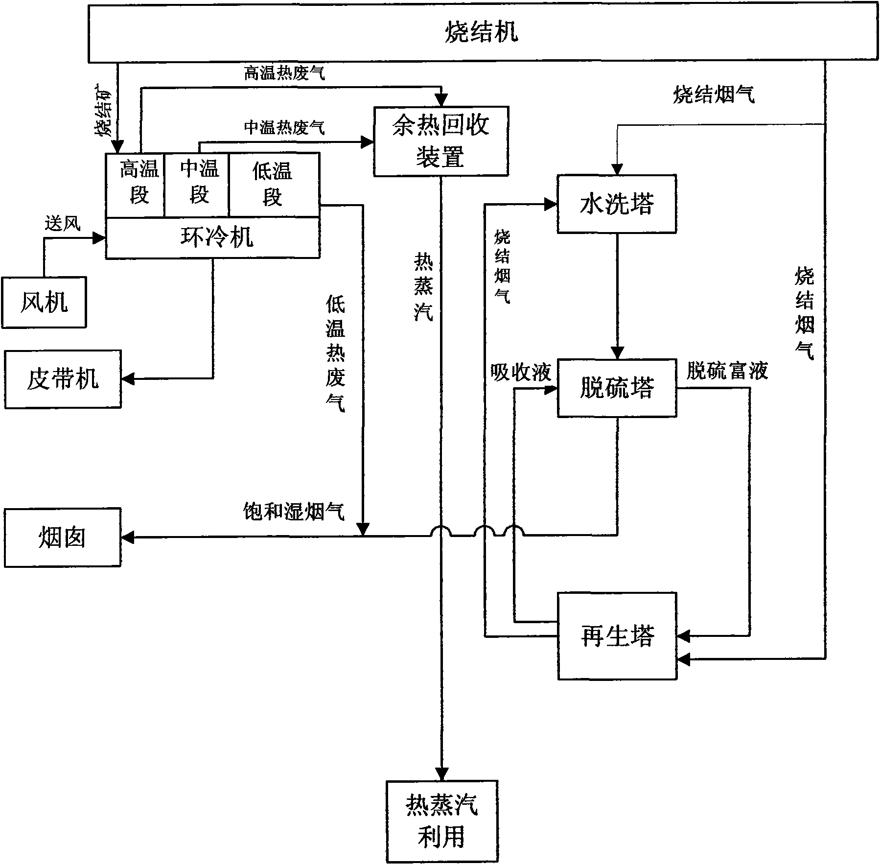
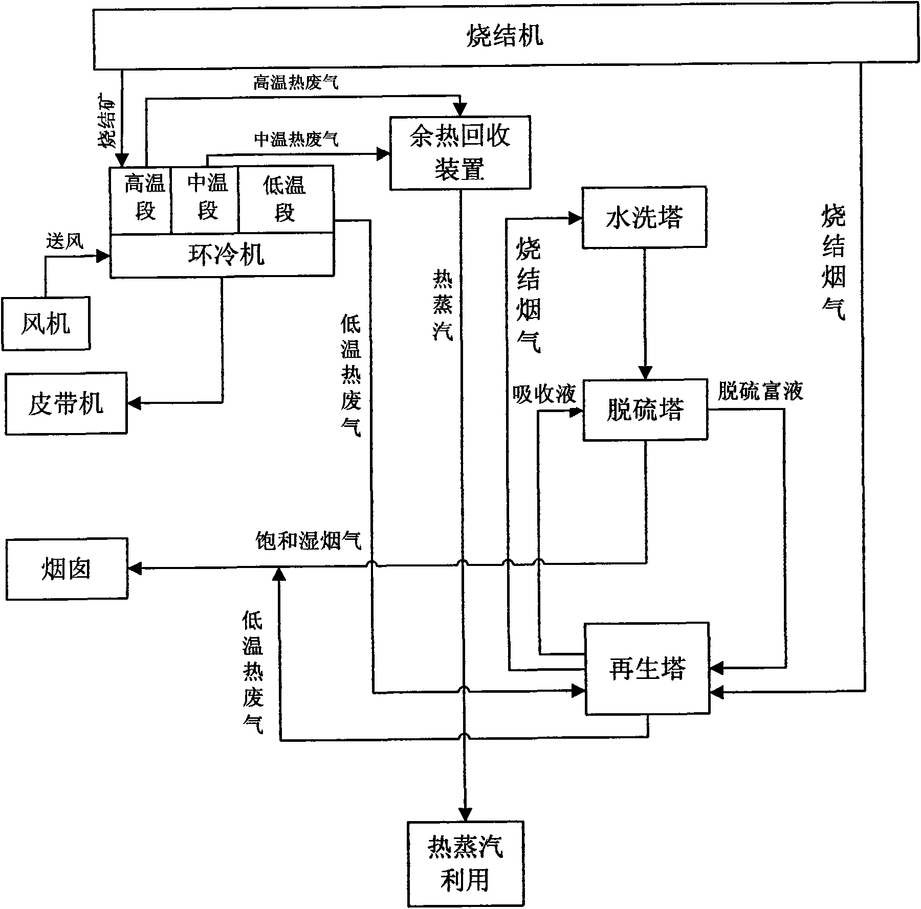
[0024] Such as Figure 5 Shown is the flue gas desulfurization process of the present invention, which is used for the flue gas desulfurization of the iron ore sintering process. Sintering machine (effective sintering area is 360m 2 ) The roasted sinter passes through the ring cooler (the cooling air volume is about 2300000Nm 3 / h) After cooling, the grains are sized and then sent to the blast furnace by a belt conveyor. The sintering flue gas (130°C ~ 180°C) discharged from the sintering process of the sintering machine is sent to the regeneration tower after being pressurized by the booster fan. In the regeneration tower, the desulfurization-rich liquid is indirectly heated by the sintering flue gas to decompose sulfur dioxide with a purity of 99.5%. The decomposed sulfur dioxide is drawn out from the top of the regeneration tower along with a large amount of water vapor. concentrated sulfuric acid). The desulfurization-rich liquid is converted into absorption liquid aft...


PUM


Abstract

The invention discloses a flue gas desulfurization process for comprehensively utilizing sintering flue gas. In the flue gas desulfurization process, a desulfurizing tower for absorbing sulfur dioxide and a regeneration tower for reclaiming desulphurization rich solution discharged by the desulfurizing tower are arranged; the sintering flue gas discharged by a sintering machine is conveyed to the regeneration tower, the sintering flue gas taken as a heat source indirectly heats the desulphurization rich solution in the regeneration tower to decompose the sulfur dioxide in the desulphurization rich solution, and an absorption liquid obtained after the desulphurization rich solution is regenerated is conveyed to the desulfurizing tower; and the discharged sintering flue gas in the regeneration tower is subjected to washing, dedusting and temperature reduction and then is sent into the desulfurizing tower, the sintering flue gas is subjected to cyclical absorption and desulphurization by the absorption liquid to obtain purified gas, and the purified gas is exhausted into atmosphere. The flue gas desulfurization process fully makes use of abandon resources, has less energy consumption, and low cost and can effectively reduce the occurrence of the phenomenon of flue gas condensation.

Description

technical field [0001] The invention relates to a comprehensive utilization process of flue gas, in particular to a comprehensive utilization process of sintering flue gas in the sintering process. Background technique [0002] Fuel (solid, gas) combustion and flue gas generated during iron ore sintering usually contain a large amount of sulfur dioxide. If the sulfur dioxide in the flue gas is not treated and discharged directly into the atmosphere, it is easy to form acid rain. Harmful to the growth of animals and plants and the living environment of human beings. [0003] Flue gas desulfurization technology is an important means to control sulfur dioxide pollution in the atmosphere, and has been commercially applied worldwide. With the development of science and technology and the continuous deepening of research, hundreds of flue gas desulfurization technologies have come out, mainly including limestone-gypsum method, rotary spray drying method, electron beam irradiation...

Claims


Application Information

Patent Timeline
Patent Type & Authority Applications(China)
IPC IPC(8): B01D53/14B01D53/50F27B21/08F27D17/00
CPCY02P10/25
Inventor 刘昌齐谭克强叶恒棣李文林
Owner ZHONGYE-CHANGTIAN INT ENG CO LTD
Learn More