
Method for preparing micro needle array by means of lithography based on tilting rotary substrate and template

A technology of microneedle array and tilt rotation, which is applied in the direction of optomechanical equipment, manufacturing microstructure devices, and the process for producing decorative surface effects, etc., can solve the problems of complex and expensive equipment and high production cost, and achieve small contact area and mechanical strength. Well-balanced features, good cutting-edge effects

Inactive Publication Date: 2011-04-20
SHANGHAI JIAOTONG UNIV
View PDF0 Cites 0 Cited by
  • Summary
  • Abstract
  • Description
  • Claims
  • Application Information

AI Technical Summary

Problems solved by technology

The advantage of this method is that the inclination angle of the microneedle can be adjusted, but the disadvantage is that the light source must be rotated while ensuring the collimation, which has the problems of complicated and expensive equipment and high production cost.

Method used


Image

  • Method for preparing micro needle array by means of lithography based on tilting rotary substrate and template
  • Method for preparing micro needle array by means of lithography based on tilting rotary substrate and template

Examples


Embodiment 1

[0026] Embodiment 1: Preparation of metal microneedle array

[0027] 1. Spin-coat 500 μm SU-8 100 on a 500 μm thick cleaned and dried glass substrate, then pre-bake and solidify, and cut flat.

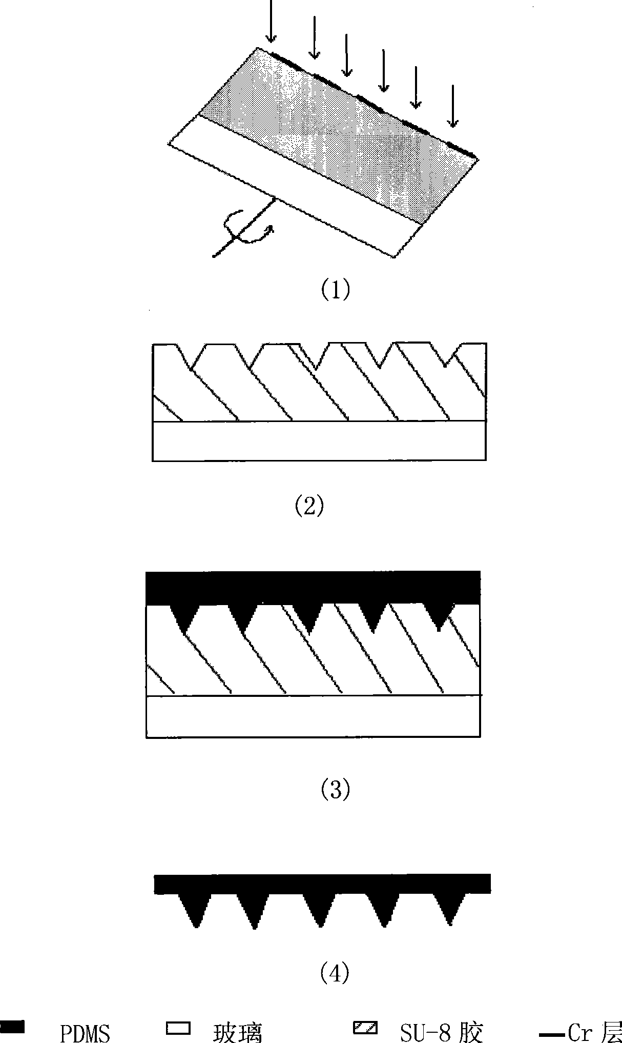
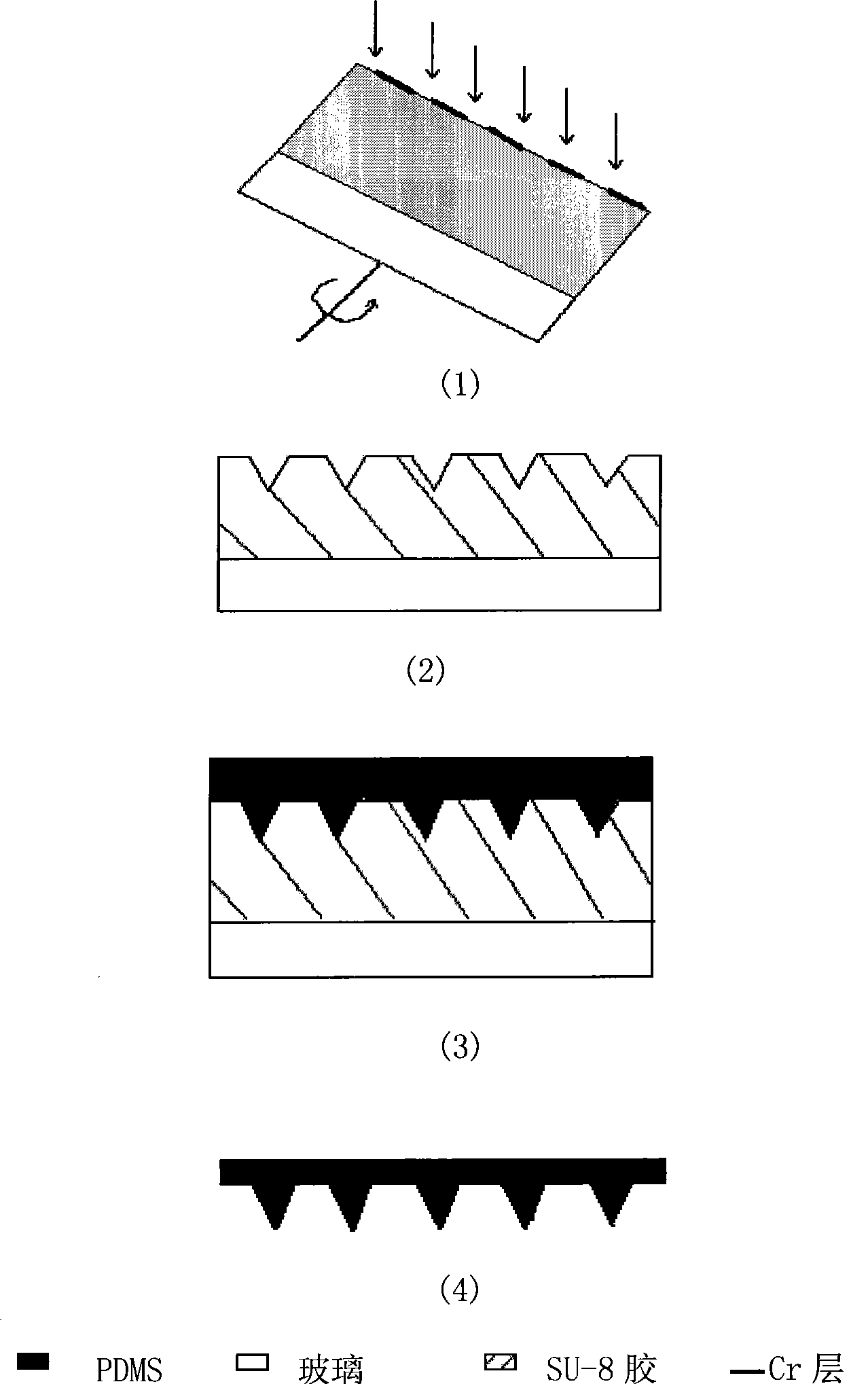
[0028] 2. The mask plate (the pattern is a solid circle, the diameter is 300 μm, the material is Cr, and the thickness is 300nm) is in close contact with the substrate and placed on the substrate fixed on the rotating shaft of the motor. The inclination angle of the substrate is 23°, and Press the speed of 250rad / min as figure 1 rotation shown.

[0029] 3. With a wavelength of 365nm, the light intensity is 3mW / cm 2 Tilt-rotation exposure under UV light for 20 minutes. Development after middle baking (soak in the developing solution of SU-8 glue for 17 minutes, you can get figure 1 The SU-8 conical concave cone structure shown in (2)).

[0030] 4. In figure 1 On the photoresist structure shown in (2), sputter 100 nanometers of Cr, 500 nanometers of Cu, and then use a current densi...

Embodiment 2

[0032] Embodiment 2: Preparation of PDMS microneedle array

[0033] At first carry out step 1-3 in embodiment 1, obtain SU-8 conical concave cone structure, then carry out following operation:

[0034] 1. In figure 1 (2) The photoresist structure is filled with PDMS (the weight ratio of PDMS body and PDMS curing agent is 10:1), and the PDMS is filled in the SU-8 conical concave cone structure mold (SU-8 glue with a diameter of 3 inches The conical-concave structure is filled with about 13 grams of PDMS).

[0035] 2. After filling, the overall structure is as follows: figure 1 As shown in (3), put the above-mentioned whole in a vacuum box to remove air bubbles for more than 1.5 hours.

[0036] 3. After removing the clean air bubbles, heat and cure it in an oven at 80 degrees Celsius for 40 minutes. Cut off the edge of the PDMS and place it in ethanol for 3 minutes. After demoulding, a PDMS microneedle array is obtained.

[0037] The conical microneedle prepared in this ex...


PUM

PropertyMeasurementUnit
diameteraaaaaaaaaa
thicknessaaaaaaaaaa
thicknessaaaaaaaaaa

Abstract

The invention relates to a method for preparing microneedle-array based on inclined rotary substrate and lithography, belonging to the micro processing technology field. The method comprises: firstly adopting the inclined rotary substrate and lithography exposal to obtain an SU-8 three-dimensional micro structure, and utilizing the excellent pattern transferring capability and demoulding capability of the PDMS to fill the PDMS into the mould of the SU-8 three-dimensional micro structure, then obtaining, the PDMS cone microneedle-array after demoulding; or sputtering the deposited metal on theSU-8 three-dimensional micro structure and then adopting the metal as a seed layer for electroform to obtain the cone microneedle-array. The inclining angle of the invention is adjustable, thus not only being capable of reducing the requirement cost of apparatus but also obtaining the standard three-dimensional micro structure provided with balanced mechanics features of each direction.

Description

technical field [0001] The invention relates to a manufacturing method in the technical field of microfabrication, in particular to a method for preparing a microneedle array based on a tilt-rotating substrate and template photolithography. Background technique [0002] Microneedle has a special role as a carrier for microfluidic biomedical applications. On the one hand, it can reduce the pain during sampling or drug delivery. On the other hand, it has the advantages of micro-sampling, micro-volume, slow release, and precise drug delivery. It has become a MEMS technology. It is one of the key technologies that urgently need to be solved in the field of biomedicine. The concept of microneedles was proposed in the 1970s. But it wasn't first tested in a laboratory until the 1990s. The initial microneedles were developed to solve the pain caused by daily injections for diabetics. Because it is quite difficult to manufacture needles with a diameter of less than 300 μm by tradi...

Claims


Application Information

Patent Timeline
Patent Type & Authority Patents(China)
IPC IPC(8): B81C1/00G03F7/00
Inventor 朱军蒋宏民陈翔
Owner SHANGHAI JIAOTONG UNIV
Learn More