Eureka AIR delivers breakthrough ideas for toughest innovation challenges, trusted by R&D personnel around the world.

Ion implantation system and ion source

An ion implantation system and ion implantation technology are applied in the field of ion implantation of ion source structure, which can solve the problems of increased space charge, high complexity and low ion productivity of an ion beam, and achieve the effect of minimizing the space charge effect.

Inactive Publication Date: 2008-04-30
SEMEQUIP
View PDF2 Cites 6 Cited by
  • Summary
  • Abstract
  • Description
  • Claims
  • Application Information

AI Technical Summary

Problems solved by technology

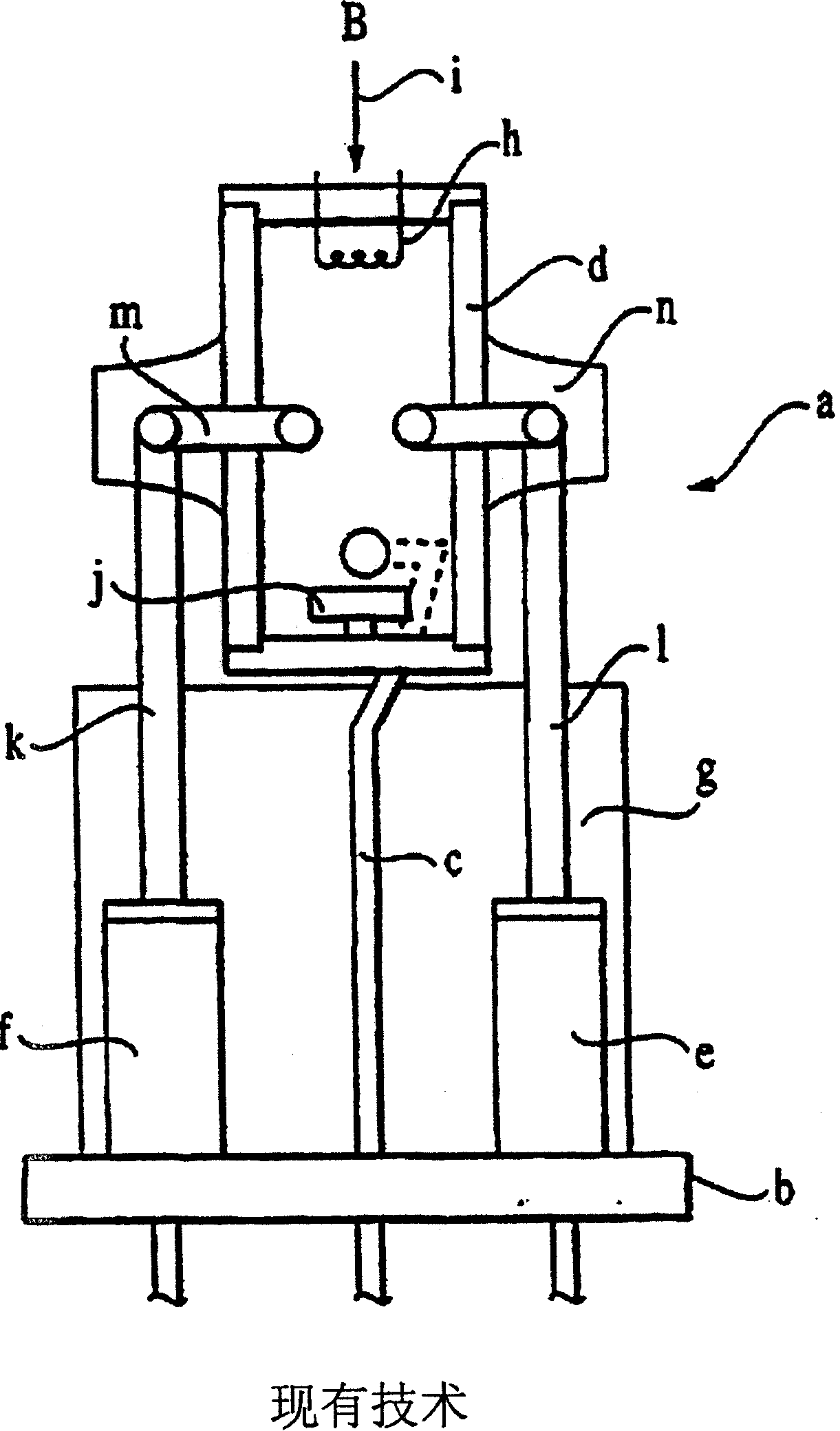
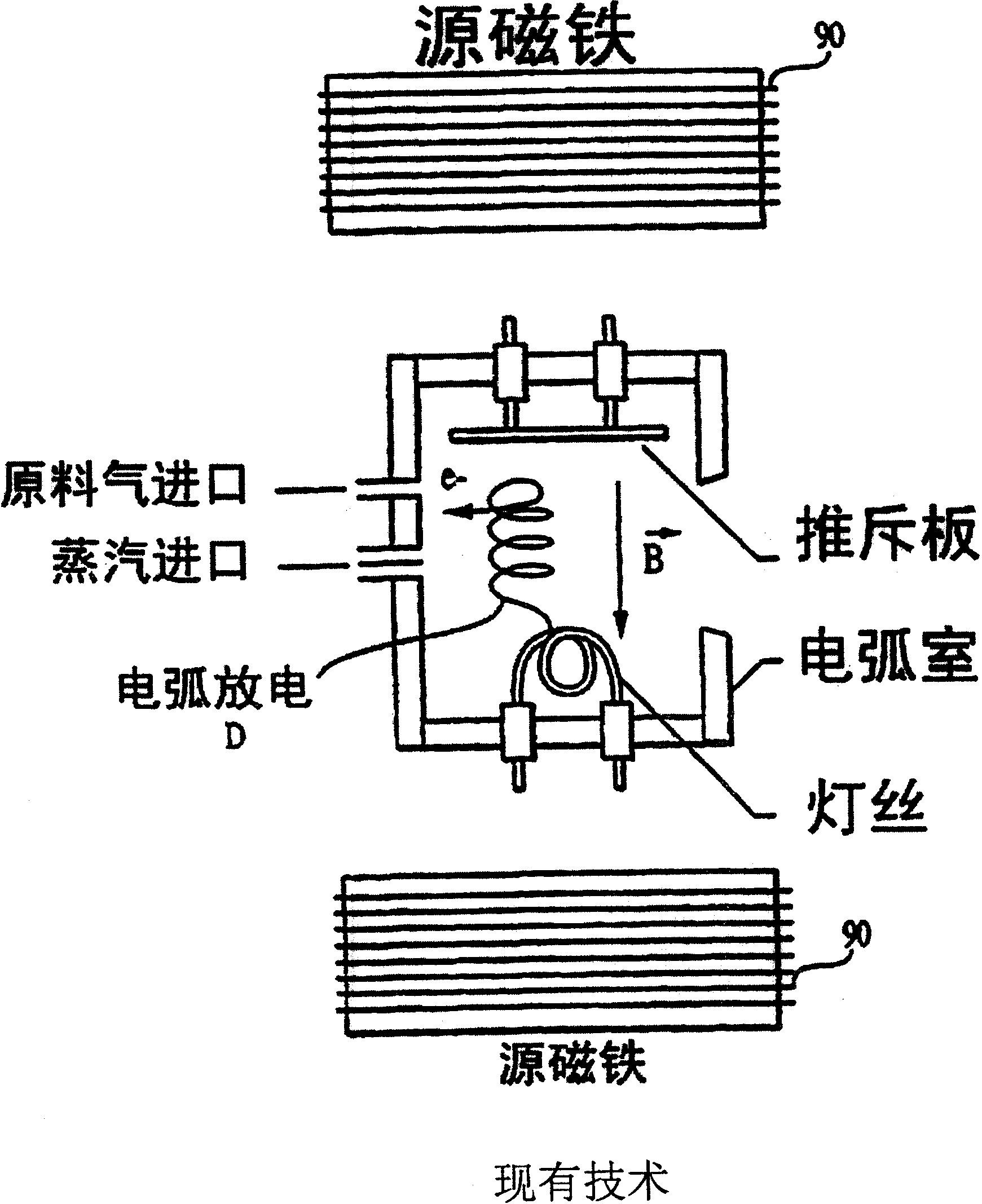
[0012] 4) Due to the presence of significant excess electrons (ie BF 3 Medium BF + , BF 2 + , F - fragments), a high extraction current density is required to enhance the space charge force during extraction and lead to increased emissivity
This time-varying ion beam potential makes charge compensation difficult to maintain in the plasma beam, as it can lead to a marked steady or even sudden loss of low-energy electrons, which typically move in a circle along the beam (attracted by the positive ion beam potential), Causes an increase in ion beam space charge
[0015] 7) The ion extraction hole cannot be extended more than 75mm (typical length between 20mm and 50mm), because this requires a significant extension of the plasma column
[0024] (1) Larger footprint (width, height and length)
[0025] (2) Expensive and highly complex
[0026] (3) Due to the large surface area of ​​the inner wall and the larger volume of the ion source, B (from the raw material gas B) is generated on the inner wall of the ion source 2 h 6 ) and P (from raw material gas PH 3 ) loss, so the ion productivity is lower
[0027] (4) Rapid accumulation of sediment in the ion source related to (3), leading to contamination and particle problems, reducing product yield
[0028] (5) Generate a large number of harmful ions implanted into the substrate, resulting in lack of implantation process control and accompanying degradation of equipment characteristics
[0029] (6) The implantation of higher currents of H+ during the implantation process (a consequence of (5)) limits the achievable dose rate and thus throughput, since the total ion current delivered to the substrate must be below a certain limit, to avoid overheating of the substrate

Method used


Image

  • Ion implantation system and ion source
  • Ion implantation system and ion source
  • Ion implantation system and ion source

Examples


Embodiment Construction

[0125] The following terms and definitions apply throughout this application.

[0126] Transverse Kinetic Energy (Er): The component of kinetic energy transverse to the direction of beam propagation, ie the extraction field direction. Er=1 / 2mv T 2 , where v T is the component of the velocity in the vertical direction of the extracted field.

[0127] Beam Noise (N): Fluctuations in beam current density, as a percentage of the average current level, at frequencies above 100 Hz.

[0128] Emissivity (ε): The total emissivity ε is the product of two emissivity, ε=ε x ε y , where in the case of using a vertical trough lens, ε x is the emissivity in the horizontal direction (along the width of the groove), ε y is the emissivity in the vertical direction. For any lens shape, ε x ε y Defined along two orthogonal directions perpendicular to the direction in which the beam travels. emissivity component e i It is defined as follows:

[0129] ε x = 2κΔ x alpha x , ε y = 2κ...


PUM

PropertyMeasurementUnit
Lengthaaaaaaaaaa

Abstract

Ion implantation with high brightness, ion beam by direct electron impact ionization of gas or vapor of eg dimer or decaborane near the exit aperture (46; 176) of the ionization chamber (80; 175). Preferably, conditions should be maintained that generate a considerable ion density and limit the ion transverse kinetic energy to within 0.7 eV (electron volts); the width of the ionization volume near the exit hole is limited to about three times the width of the exit hole; Exit holes are very slender; magnetic fields are avoided or limited; ion beam noise is kept low; conditions within the ionization chamber are maintained to prevent arcing from forming. Ions generated from the ion source are delivered to the target surface and implanted by ion beam optics, such as a batch injector in Fig. (20), or a continuous injector; in some cases, ion acceleration-deceleration beamlines are used Clusters are more beneficial. The invention also discloses the structure of the electron gun, the belt electron source and the structure of the ionization box. The present invention demonstrates the characteristics of the formation of drain extension and planar mesa doping of semiconductor devices, such as CMOS (Complementary Metal Oxide Semiconductor) devices.

Description

technical field [0001] The present invention relates to ion source, ion implantation, especially ion implantation with high brightness, low emissivity ion source, acceleration-deceleration conveying system and improved structure of ion source. Background technique [0002] The following patent application, the contents of which are incorporated herein by reference, describes the background of the invention: Invented by Thomas N. Horsky, Serial No. 60 / 267,260, filed 2001 Provisional Patent Application, February 7, entitled "Ion Source for Ion Implantation"; inventor Thomas N. Horsky, Serial No. 60 / 257,322, filed 2000 Provisional Patent Application, December 19, entitled "Ion Implantation"; inventor Thomas N. Horsky, filed December 13, 2000, entitled "Ion Source for Ion Implantation" , System and Method" US Patent Application No. 00 / 33786 (filed on November 30, 2000), which has the same references. The referenced patent for the United States is a continuation of my US Provis...

Claims


Application Information

Patent Timeline
IPC IPC(8): H01J37/317H01J37/08H01J27/20H01L21/265
CPCH01J2237/082H01J37/3171H01J37/08H01J2237/0812H01J2237/0473H01J27/205H01J2237/0475
Inventor T·N·霍尔斯基B·C·科恩W·A·克鲁尔G·P·小萨科
Owner SEMEQUIP
Why Eureka
Eureka Blog
Learn More