
Thermal transfer device with spiral fluid pathways

a technology of fluid pathway and thermal transfer device, which is applied in the direction of semiconductor/solid-state device details, lighting and heating apparatus, laminated elements, etc., can solve the problems of lowering the thermal transfer rate, affecting the overall efficiency of the thermal transfer device, and limiting the way this has been achieved to date, so as to achieve efficient and effective cooling of objects

Active Publication Date: 2017-02-14
AAVID THERMALLOY LLV
View PDF25 Cites 0 Cited by
  • Summary
  • Abstract
  • Description
  • Claims
  • Application Information

AI Technical Summary

Benefits of technology

This patent describes a thermal transfer device that helps to cool down objects that are prone to overheating, such as computer chips. The device has a passageway where a heat transfer fluid flows through in thermal contact with a surface. The passageway has at least two spiral passages, which increases the surface area exposed to the fluid and makes the device more efficient. This longer flow path provides more cooling to the surface, and the terms "spiral" and "helical" are used interchangeably herein.

Problems solved by technology

There is a limit, however, as to how this has been accomplished to date.
The addition of fins, however has the unwanted effect of interfering with the flow of the thermal transfer fluid, thereby lowering the rate of thermal transfer and impairing the overall efficiency of the thermal transfer device.

Method used


Image

  • Thermal transfer device with spiral fluid pathways
  • Thermal transfer device with spiral fluid pathways
  • Thermal transfer device with spiral fluid pathways

Examples


Embodiment Construction

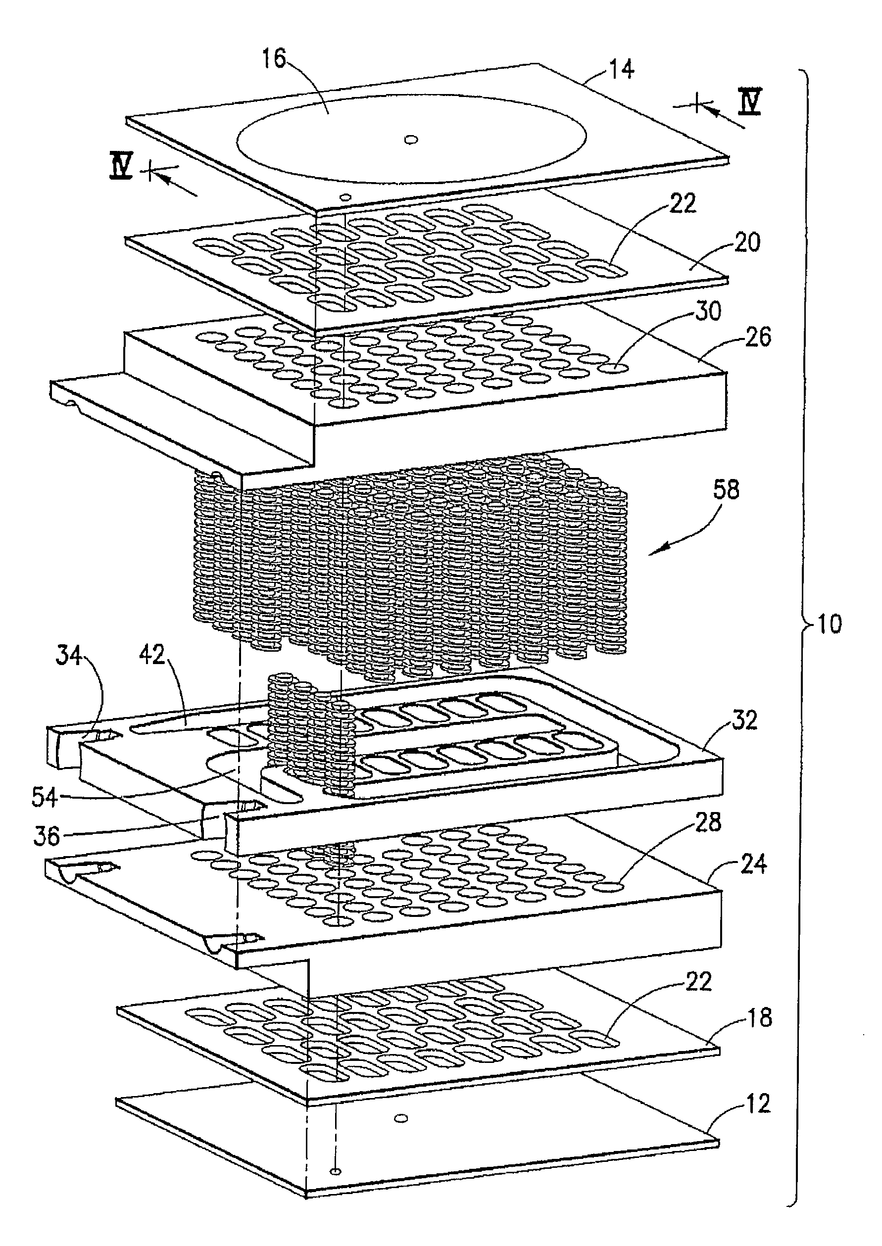
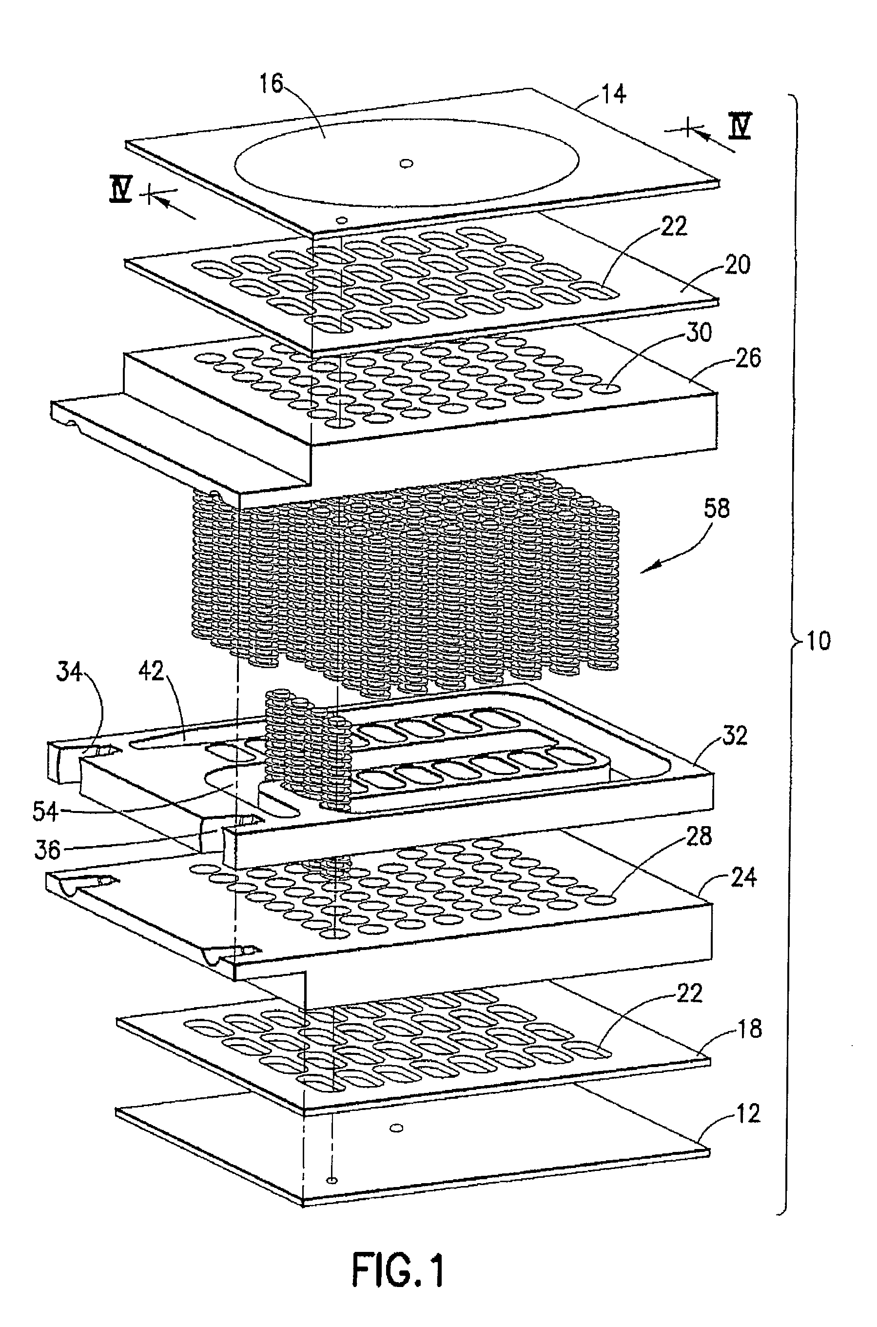
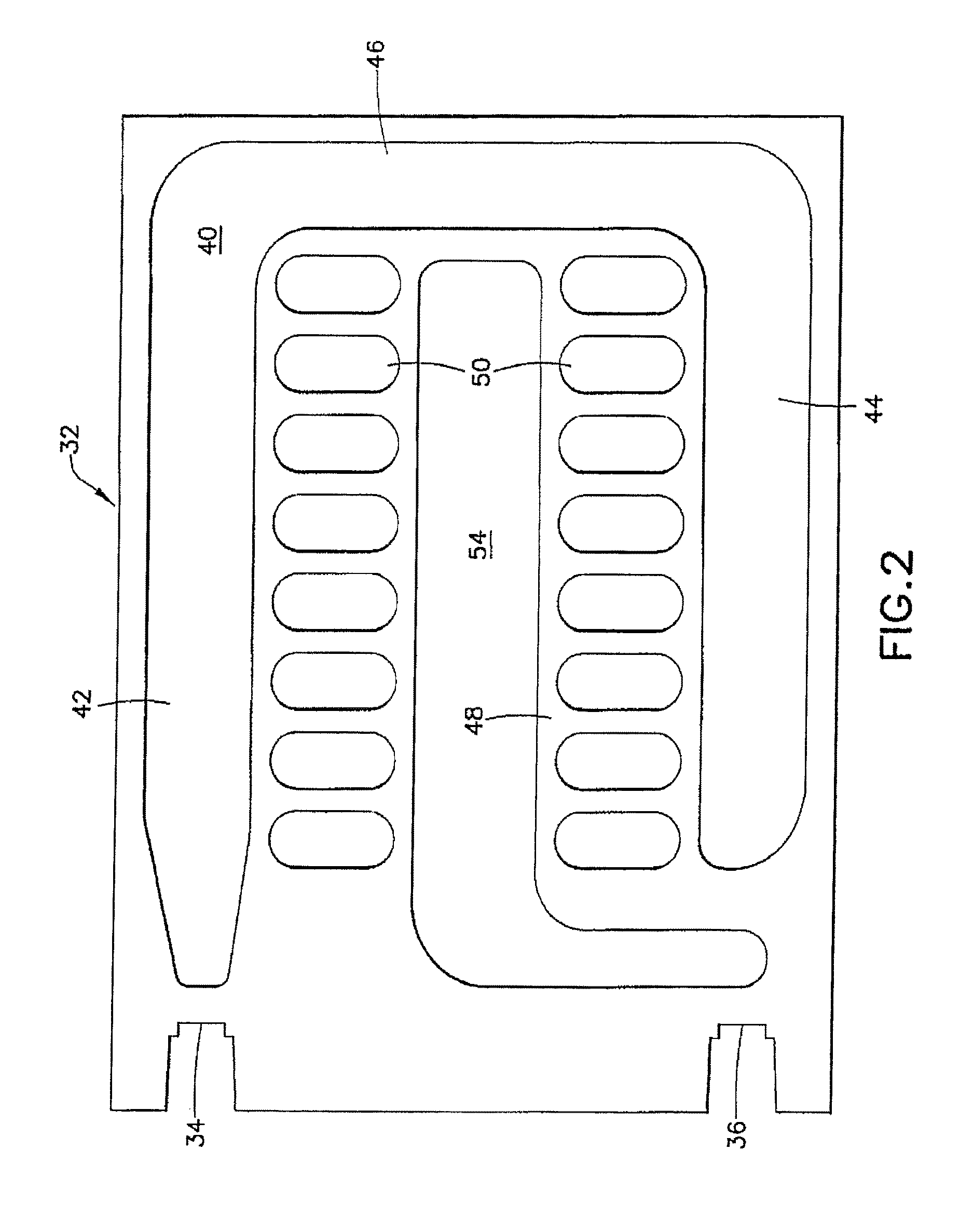
[0020]In accordance with a preferred embodiment of the invention, there is shown, generally at 10, a thermal transfer device, or “cold plate” in accordance with the invention. Thermal transfer device 10 includes a pair of opposed thermal transfer surfaces 12, 14. Thermal transfer surfaces 12, 14 are made of a suitable thermal transfer material, such as, copper, aluminum and alloys of steel. Thermal transfer surfaces 12, 14 are preferably generally planar and form the outer surfaces through which heat transfer activity takes place. Each thermal transfer surface 12, 14 contacts an object to be cooled, such as shown (diagrammatically) with respect to the outer surface of heat transfer surface 14 by circle 16. Although preferably generally planar, to provide the widest possible utility of thermal transfer device 10, thermal transfer surfaces 12, 14 may be formed in any desired shape, such as to conform to the shape of a specific object to be cooled. In the preferred embodiment, where th...


PUM


Abstract

A thermal transfer device comprising a thermal transfer surface and a passageway for conducting a thermal transfer fluid from an inlet to an outlet while passing in thermal contact with the thermal transfer surface. The passageway has at least two spiral passages and a connection channel connecting the at least two spiral passages to permit flow of the heat transfer fluid from a first spiral passage to a second spiral passage; thereby forming a path for the flow of the thermal fluid from the inlet, through the passageway, along the first spiral passage to the connection channel, then along the connection channel to the second spiral passage, and then to the outlet.

Description

BACKGROUND OF THE INVENTION[0001]1. Field of the Invention[0002]This invention is directed to a thermal transfer device, such as a cold plate for use in indirectly cooling objects with a cooling liquid and, more particularly, to a thermal transfer device having spiral fluid pathways for efficiently conducting a cooling fluid into indirect thermal contact with an object to be cooled.[0003]2. Description of the Related Art[0004]Cold plates are well-known thermal transfer devices used for cooling objects that generate excessive heat, such as, without limitation, computer chips. Cold plates are generally placed into thermal contact with the object to be cooled, and pass a cooling liquid over a surface which separates the liquid from the actual object to be cooled. In this fashion, heat may be transferred between the fluid and the object, without the fluid ever coming into direct contact with the object.[0005]Direct contact is generally avoided, because the properties of many cooling flu...

Claims


Application Information

Patent Timeline
Patent Type & Authority Patents(United States)
IPC IPC(8): F28F1/00H05K7/20F28F1/36H01L23/473F28F3/08F28F1/40F28F13/12F28F3/06F28D9/00F28D7/02F28D21/00
CPCF28F1/00F28D7/026F28D9/0075F28F1/36F28F1/40F28F3/06F28F3/086F28F13/12H01L23/473H05K7/20254F28D2021/0029H01L2924/0002H01L2924/00
Inventor MORUZZI, MARCO
Owner AAVID THERMALLOY LLV
Learn More