
cut off cutting tool

A cutting tool and metal cutting technology, applied in the direction of tool holder, cutting blade, manufacturing tool, etc., can solve the problems of coolant limitation, cutting cutting tool flat, etc., and achieve the effect of high cutting efficiency and good cooling effect.

Active Publication Date: 2022-06-03
KENNAMETAL INC
View PDF0 Cites 0 Cited by
  • Summary
  • Abstract
  • Description
  • Claims
  • Application Information

AI Technical Summary

Problems solved by technology

[0006] However, there is a problem with parting-off cutting tools compared to other cutting tools, which are particularly bulky: These are particularly flat, especially at the points to be cooled
The delivery of coolant to the cutting area is thus limited

Method used


Image

  • cut off cutting tool
  • cut off cutting tool
  • cut off cutting tool

Examples


Embodiment Construction

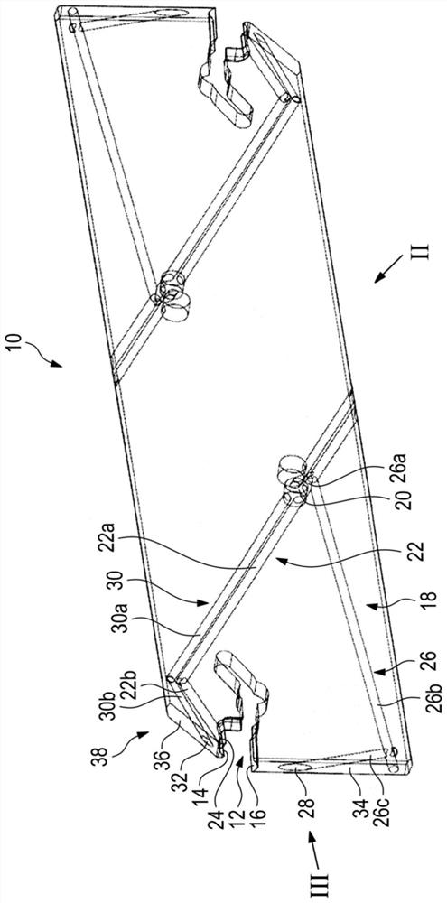
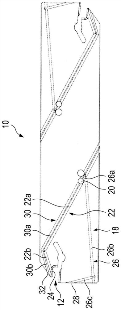
[0036] Figures 1 to 3 show a parting cutting tool 10 for cutting metal working.

[0037] The severing cutting tool 10 may also be referred to as a severing sword.

[0039] The severing cutting tool 10 also includes an internal coolant supply system 18 for supplying coolant to the cutting area.

[0040] A coolant supply opening 20 is provided on the parting cutting tool 10 on the part of the tool holder or on the lathe for this purpose.

[0042] The severing cutting tool 10 is thus supplied with coolant through the coolant supply aperture 20.

[0044] The coolant lines 22, 26, 30 are here in fluid connection with the associated coolant outlets 24, 28, 32, respectively.

[0045] Furthermore, these coolant lines run within the cutting tool 10 for severing.

[0047] The first coolant outlet is here configured to be in fluid connection with a coolant inlet of a cutting insert, not shown in detail.

[0049] The second coolant outlet 28 is provided at the workpiece-side end face 34 of the...


PUM


Abstract

A parting off cutting tool (10) for cutting metal machining is described. The parting off cutting tool has a holder seat (12) for receiving a cutting insert and an internal coolant supply system (18) for supplying coolant to the cutting zone. The coolant supply system (18) here comprises at least three coolant outlets (24, 28, 32). These coolant outlets (24, 28, 32) are connected to coolant supply ports (20) through at least two separate coolant lines (22, 26, 30) extending within said parting cutting tool (10). ) fluid connection.

Description

parting cutting tool technical field [0001] The present invention relates to a parting cutting tool for cutting metal working with a Clamping seat with an internal coolant supply system for supplying coolant to the cutting area, the coolant supply system package Include at least one coolant line extending in the severing cutting tool. Background technique [0002] Such parting cutting tools are known from the prior art. Such a parting cutting tool is used for parting clamping in Turned parts on a lathe. Parting cutting tools can also be used to make grooves. For this there are tools in different widths, These widths generally correspond to the groove widths to be produced. [0003] As in other cutting tools for cutting metal processing, in the cutting tool for cutting, it is The cutting tool is equipped with good cutting performance, thus guaranteeing a high stock removal rate and thus fast execution of manufacturing tasks. Shi. At the same time, a high service...

Claims


Application Information

Patent Timeline
Patent Type & Authority Patents(China)
IPC IPC(8): B23Q11/10
CPCB23Q11/10B23B27/086B23B27/10B23B29/043B23B27/04B23B27/083B23B2200/3627B23B2250/12B23B2260/0785
Inventor F.比克曼I.考夫曼
Owner KENNAMETAL INC
Learn More