Microsensor material and methods for analyte detection

a microsensor and analyte technology, applied in the field of chemical or biological analytes detection, can solve the problems of reduced performance and eventual failure, difficult to obtain sensors, and not ideally suited to all applications, and achieve the effects of increasing the free volume of polymeric materials, and free volum

Inactive Publication Date: 2014-09-09
CANTIMER +1
View PDF31 Cites 3 Cited by
  • Summary
  • Abstract
  • Description
  • Claims
  • Application Information

AI Technical Summary

Benefits of technology

[0020]In another aspect, a method for detecting the presence of analyte using a compositon as described above is provided. The method comprises providing a sensor material as described above, where the polymeric material has a free volume that is reduced upon interaction with the solid material and increased when the interaction with the solid material is reduced, exposing the sensor material to the analyte, which analyte competes with the polymeric material for interaction with the solid material, thereby reducing the interaction between the polymeric material and the solid matrix and increasing the free volume of the polymeric material, and detecting the increase in the free volume of the polymeric material. The increase in the free volume of the polymeric material corresponds to the presence of the analyte.

Problems solved by technology

While conventional sensors often perform adequately for their intended uses, they are not ideally suited to all applications.
The repeated expansion and contraction of the sensor matrix due to the influx and efflux of analytes weakens the sensor matrix and leads to reduced performance and eventual failure.
It is also difficult to obtain sensors having uniform thin films of a matrix, which leads to variability among sensors.
Thick films are generally undesirable because they require an extended period of time to absorb the target analyte, thus increasing the amount of time required for a response to an analyte.

Method used


Image

  • Microsensor material and methods for analyte detection
  • Microsensor material and methods for analyte detection
  • Microsensor material and methods for analyte detection

Examples


example 1

Sensor Material to Detect Hydrogen Cyanide

[0092]An exemplary sensing material was comprised of a kertain matrix in combination with thiolated colloidal gold particles. α-keratins assemble intermediate filaments by forming multiple disulfide cross-links among the molecules (Nelson and Cox (2005) Principles of biochemistry, W. H. Freeman and Co.). Alkanethiol monolayers form on gold surfaces by strong coordination of alkanethiol compounds to gold by self-assembly (Bain (1989) J. Am. Chem. Soc. 111:321-335; Nuzzo and Allara (1983) J. Am. Chem. Soc. 105:4481-4483; Whitesides and Laibinis (1990) Langmuir 6:87-96).

[0093]Keratin was mixed first with 2-mercaptoethanol to reduce disulfides to sulfhydryls, and then with colloidal gold to form a self-assembled matrix of nanogold-keratin via gold thiolate coordination. The source of keratin was VariKer 100 keratin powder (Variati and Company, Milan, Italy). Colloidal gold source was particles with a diameter of 20 nm in aqueous suspension (Sigm...

example 2

Exposure of the Sensor Material to Different Concentrations of HCN

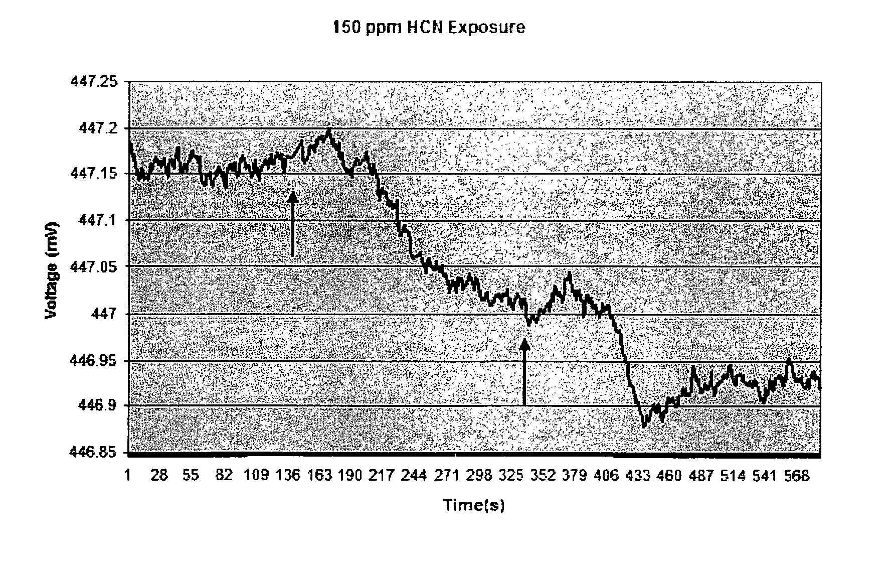
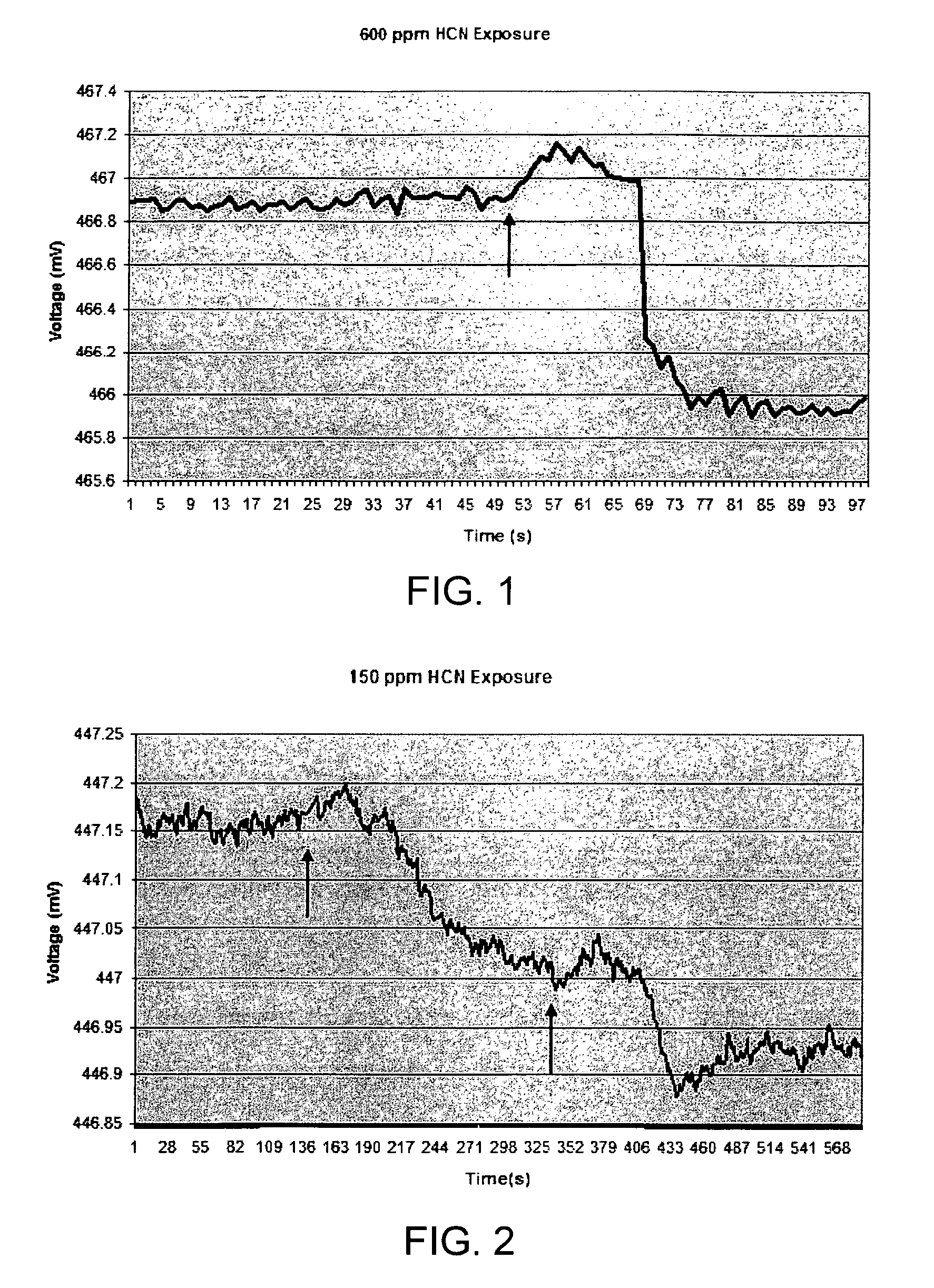
[0099]Sensor material as described in Example 1 was also exposed to lower levels of HCN and the increase in polymer volume was detected using an EPM sensor. FIG. 2 shows the initial response of the sensor material to an exposure of approximately 150 ppm HCN. H2SO4 was added to KCN to evolve HCN at 139 second, as indicated by the arrow. As with the experiments described in Example 1, the initial sensor response was an increase in voltage, indicating that the microcantilever moved toward (into) the sensor material. The initial increase in sensor voltage was followed by a decrease in voltage, as before. The overall time frame for the response to the 150 ppm exposure was about 210 second, or approximately 5 times the length on the response time for 600 ppm HCN. The net voltage change from initial reading to final reading was approximately 0.15 mV, or ⅙ of the previous 600 ppm voltage response. The estimated net cantilever...

example 3

Negative Controls

[0101]Several negative control experiments were performed to confirm that the analyte sensor operated as predicted. The negative control experiments were performed in the absence of analyte, polymer matrix, or particles. The results of the experiments indicated that the analyte sensor requires both a polymer matrix components and solid particle component to respond to an analyte in the manner described. The polymer matrix or solid particle, alone without the other component, is ineffective as an analyte sensor, supporting the theory of operation.

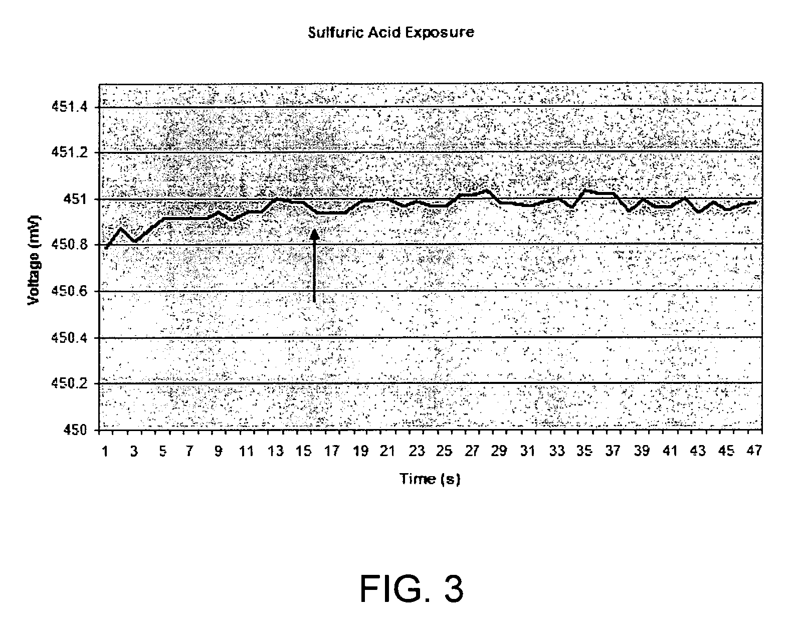
[0102]1. No Analyte (H2SO4 Vapor Only)

[0103]Similar sensor material to that used in Examples 2 and 3 was exposed to H2SO4 vapors only, in the absence of a KCN analyte. Here, the sensor was present in the chamber when sulfuric acid was injected in through a rubber membrane with a syringe. The amount of acid vapor was similar to that present in the 600 ppm-experiment of Example 1. The results are shown in FIG. 3, with the arro...


PUM

PropertyMeasurementUnit
diameteraaaaaaaaaa
diameteraaaaaaaaaa
diameteraaaaaaaaaa

Abstract

The compositions and methods relate to an organic polymer-inorganic particle sensor material for detecting analytes. Interactions between the polymer and the particles are affected by the presence of analyte, which displaces the polymer and increases its free volume. This change in free volume can be detected, e.g., using an embedded piezoresistive microcantilever (EPM) sensor. Analytes that can be detected include noxious substances, such as hydrogen cyanide gas and carbon monoxide.

Description

CROSS-REFERENCE TO RELATED APPLICATIONS[0001]This application is a U.S. National Stage of International Patent Application No. PCT / US2008 / 000672, filed Jan. 18, 2008, which claims the benefit of U.S. Provisional Application No. 60 / 881,754, filed Jan. 19, 2007, and U.S. Provisional Application No. 60 / 926,474, filed Apr. 27, 2007, all of which are hereby incorporated by reference.TECHNICAL FIELD[0002]The present subject matter relates to compositions and methods for detecting chemical or biological analytes, and to relate to sensors using the compositions. More particularly, the subject matter relates to a polymer-particle sensor in which analytes compete with the polymer for interaction with the particles, and the presence of analyte results in a detectable change in the free volume of the polymer.BACKGROUND[0003]Chemical or “analyte” sensors typically employ a sensing component that is physically or chemically modified in the presence of an analyte. Such sensors include resistance / c...

Claims


Application Information

Patent Timeline
Patent Type & Authority Patents(United States)
IPC IPC(8): G01N27/12G01N5/02G01N33/00G01N29/036
CPCG01N29/036G01N2291/0257Y10T436/16Y10T436/15Y10T436/19Y10T436/172307Y10T436/205831Y10T436/153333Y10T436/204998Y10T436/17Y10T436/196666
Inventor PORTER, TIMOTHY L.STEWART, RAYVAIL, TIMOTHY L.
Owner CANTIMER
Why Eureka
Try Eureka