Ultra-hard composite material and method for manufacturing the same
a composite material and ultra-hard technology, applied in the direction of coatings, etc., can solve the problems of insufficient toughness, thermal resistance, anti-corrosion, anti-adhesion, anti-corrosion, anti-corrosion, etc., and achieve the effect of improving the hardness and thermal resistance of the composite material, reducing the toughness, and improving the hardness of the composite material
- Summary
- Abstract
- Description
- Claims
- Application Information
AI Technical Summary
Benefits of technology
Problems solved by technology
Method used
Image
Examples
example 1
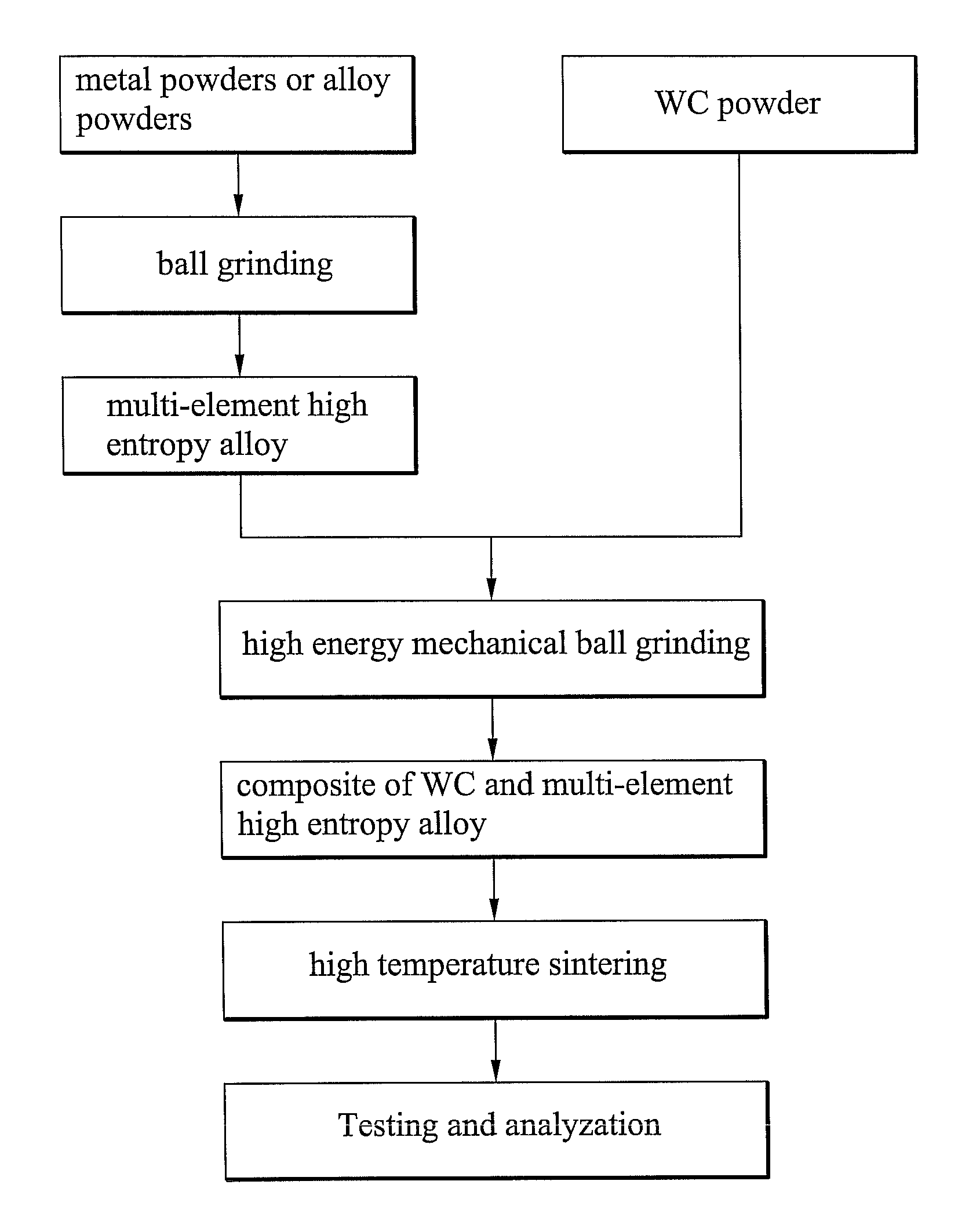
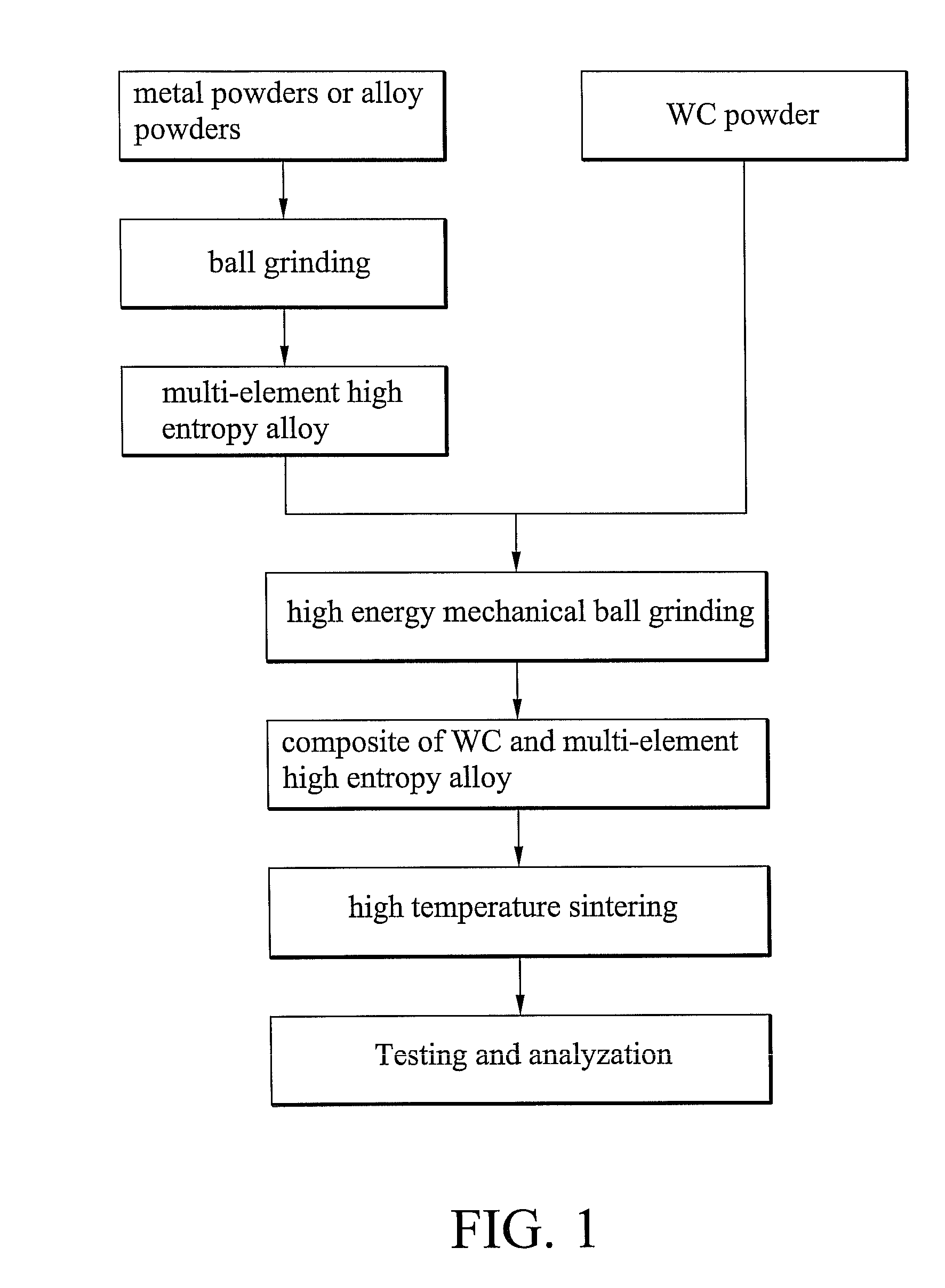
[0026]FIG. 1 shows the sintering process of Example 1. First, several pieces of pure metal or alloy powder were ball grinded to form a multi-element high-entropy alloy powder. Second, different ratios of the multi-element high-entropy alloy powder and WC powder were mixed and ball grinded to form evenly mixed powders. Subsequently, the WC / multi-element high-entropy alloy mixtures were green compacted, and sintered at a high temperature to form ultra-hard composite materials. Lastly, the composite materials were tested and analyzed. In Example 1, the high-entropy alloy powders were composed of aluminum, chromium, copper, iron, manganese, titanium, and vanadium. The component ratios of A serial alloys according to Taguchi's method (L827) as an orthogonal array were tabulated as in Table 1.
[0027]
TABLE 1AlloyserialNo.componentAlCrCuFeMnTiVA1Molar ratio1111111Molar14.2814.2814.2814.2914.2914.2914.29percentageA2Molar ratio1110.20.20.20.2Molar26.3226.3226.325.265.265.265.26percentageA3Mola...
example 2
[0030]FIG. 1 also shows the sintering process of Example 2. Six element powders such as aluminum, chromium, cobalt, copper, iron, and nickel were ball grinded to form the multi-element high-entropy alloy powder. The component ratios of B serial alloys were tabulated as in Table 3. For of the B2 powder example, the relation between the ball grinding time and the crystal structure was analyzed by X-ray diffraction, whereby a diagram is shown in FIG. 3. In reference to FIG. 3, complete alloying, such as a single FCC phase solid solution, can be achieved by at least 24 hours of ball grinding.
[0031]
TABLE 3Alloyserial No.ComponentAlCrCoCuFeNiB1Molar ratio0.311111Molar5.7018.8618.8618.8618.8618.86percentageB2Molar ratio0.511111Molar9.118.1818.1818.1818.1818.18percentageB3Molar ratio0.811111Molar13.8017.2417.2417.2417.2417.24percentage
[0032]Table 4 shows the mixtures composed of different ratios of B serial alloys and WC powder. FIG. 4 shows X-ray diffraction results of the mixture in Table...
example 3
[0038]FIG. 1 also shows the sintering processes of Example 3. Element powders such as carbon, chromium, nickel, titanium, and vanadium were ball grinded to form multi-element high-entropy alloy powders. The component ratio of C1 alloy was tabulated as in Table 7. FIG. 6 shows an X-ray diffraction diagram of alloy C1, whereby the alloy powder was completely alloyed as a single BCC phase solid solution after ball grinding.
[0039]
TABLE 7Alloy serialNo.componentCCrNiTiVC1Molar ratio0.31211Molar percentage5.7018.8637.7218.8618.86
[0040]The sintering density and hardness in room temperature of the testing samples composed of different ratios of Cl alloy powder and WC powder sintered at different temperatures were tabulated as in Table 8. For example, for the testing sample of 20% Cl alloy and 80% WC powder, the hardness of the testing sample reached HV 1825. For example, for the testing sample of 15% Cl alloy and 85% WC powder, the hardness of the testing sample reached Hv 1972. The hardnes...
PUM
| Property | Measurement | Unit |
|---|---|---|
| temperature | aaaaa | aaaaa |
| temperature | aaaaa | aaaaa |
| ultra-hard | aaaaa | aaaaa |
Abstract
Description
Claims
Application Information
 - R&D
- Intellectual Property
- Life Sciences
- Materials
- Tech Scout
- Unparalleled Data Quality
- Higher Quality Content
- 60% Fewer Hallucinations
Browse by: Latest US Patents, China's latest patents, Technical Efficacy Thesaurus, Application Domain, Technology Topic, Popular Technical Reports.
© 2025 PatSnap. All rights reserved.Legal|Privacy policy|Modern Slavery Act Transparency Statement|Sitemap|About US| Contact US: help@patsnap.com


