
Wireless scleral search coil including systems for measuring eye movement and methods related thereto

a scleral search coil and wireless technology, applied in the field of eye movement measurement devices, systems and methods, can solve the problems of high cost, fragile wired scleral contact lenses used in humans, and delicate wires, so as to increase the comfort level of the subject, facilitate the configuration, and increase the effect of comfor

Inactive Publication Date: 2011-06-28
THE JOHN HOPKINS UNIV SCHOOL OF MEDICINE
View PDF3 Cites 20 Cited by
  • Summary
  • Abstract
  • Description
  • Claims
  • Application Information

AI Technical Summary

Benefits of technology

[0030]The wireless coil system of the present invention will advantageously allow freedom of head movement, and measurement of eye movements in situations not currently possible with wired search coil systems. High head acceleration stimuli are of increasing importance in oculomotor research, and the compact, light weight system afforded by the present invention is much better able to deliver accurate data under these experimental conditions.
[0040]The wireless search coil assembly and systems of the present invention also would have beneficial advantages in regards to animal studies. As to animal studies the wireless search coil of the present invention would simplify surgical procedures and this along with the portability and size of the related systems would also simplify the experimental setup.

Problems solved by technology

This wire is delicate and is a major source of coil defects.
Also, this wire is a source of discomfort for the subject as it rubs the edges and inner surfaces of the eyelids and may become entangled in the eyelashes.
In addition, this wire can contribute to motion artifacts, since the eyelids can push the wire and, therefore, move the coil and lens on the eye (Bergamin O, Roberts D C, Ramat S, Straumann D, Zee D Z. Influence of orientation of exiting wire of search coil annuli on torsion following saccades.
The wired scleral contact lenses used in humans are fragile and expensive and typically last for only a few recording sessions.
Experiments typically call for a coil on each eye, so a continuous and costly supply of these lenses must be maintained.
Further, wire breakage during experiments causes delays, loss of data, and sometimes, due to time constraints, early termination of the experiment.
Surgically implanted coils used in animal studies are extremely expensive due to their risky and labor intensive nature and are also susceptible to breakage.
This is an added source of infection and malfunction.
Rubbing of the wire inside the animal's head can be a source of discomfort and infection.
The mechanical load of the wire can also cause eye movement problems and strabismus.
This is such a great restriction that as a general rule, no practical attempt is made to make head-free measurements while using search coils.
The large field coil structure also imposes limits on the location of coil experiments.
Typically, such coil systems are not portable.
All of this severely restricts the use of search coil systems in novel locations, situations, and orientations.
Another potential problem with existing search coil systems is slippage of the contact lens in human subjects, especially torsionally.
Without being bound to any particular theory, it is believed that some of this effect may be due to irritation of the eyes from the coils, and in particular from the connecting wires leading from the scleral coils as this is almost always the part of the coils that cause the most discomfort and “awareness” of something in the eye.
An ill-positioned connecting wire tends to slide across the lower lid or the lashes, which can be quite annoying and could easily lead to a desire to reduce eye velocity and the duration of eye movements.)
The disadvantage of the wire running from the scleral eye coil to the instrumentation has been recognized by several groups.
This elegant solution is useful only for horizontal and vertical eye movements, and cannot be easily extended to include torsional measurements.
Small movements of the eye relative to the secondary detector coil cause large errors in the measurements.
Moreover, these systems have seen only very limited use in a few labs.
BOG, which uses electrodes placed near the eyes, is relatively easy to use, but suffers from lack of sensitivity due to muscle noise, drift due to changes in the skin-electrode interface, and changes in gain and bias due to changes in corneo-retinal potential with variations in ambient lighting.
EOG is unsuitable when high resolution and accuracy are required, it cannot measure torsion, and it provides poor vertical measurements.
However, most IR tracker systems cannot accurately measure eye movements greater than approximately ±15 to ±20 degrees horizontally, and less vertically.
These systems also can be difficult to calibrate, and do not measure torsion.
No video based system today approaches the search coil's ability to measure horizontal, vertical, and torsional eye movements at 1000 Hz and above.
In addition to these limitations, an inherent limitation of VOG is that a camera needs to acquire an image of the eye, and in some situations this maybe difficult or impossible.
Droopy eyelids or narrow eye openings cause problems for VOG, as do blinking, squinting, and, obviously, closed eyes.
Wearing glasses is not permitted with many types of VOG systems, and patching or occluding an eye may not be permitted.
A camera, or some form of optics or right angle prisms, must always be in the field of view, which can be unacceptable in many circumstances.
The use of a stereoscopic video apparatus to present visual stimuli (VR: virtual reality) would present a problem, unless the apparatus was specifically designed to accommodate VOG.
There are also several very common experimental setups in which a video system is inconvenient or unacceptable.
It is not uncommon to evaluate patients with fourth nerve palsies, which cause the eyes to be misaligned.
This may be problematic because, depending on the configuration of the particular VOG system, covering of the eye may preclude the recording of its position.
Video systems would at the least complicate the determination of eye position, or at worst not be usable at all.
Illumination of the eye is required for the camera to capture an image, however, many evaluations require absolute darkness so that the subject has no fixation targets.
While infrared illumination results in decreased visibility of the illumination, it may not eliminate it.
IR LEDs are sometimes visible as a dim red glow to a subject that is dark adapted, and this can compromise the conditions of the evaluation.
In addition, it can be very difficult to get an image of the eye that is good enough to perform torsional eye movement analysis.
Higher-wavelength IR illumination is less visible to the subject, but it also results in a more washed-out (lower contrast) image of the iris, leading to poorer torsional tracking.
Another shortcoming with VOG is the need to mount the imaging camera to the subject's head, possibly interfering with head motion.
Furthermore, if the camera is not very firmly attached, jitter in the resulting image will degrade the quality of the measurement.
This is a significant problem that severely restricts the use of video in situations where free and rapid head and body motions occur.
The more effective methods to stabilize the device on the head are also quite uncomfortable, requiring a biteboard or clamping to the head.

Method used


Image

  • Wireless scleral search coil including systems for measuring eye movement and methods related thereto
  • Wireless scleral search coil including systems for measuring eye movement and methods related thereto
  • Wireless scleral search coil including systems for measuring eye movement and methods related thereto

Examples


Embodiment Construction

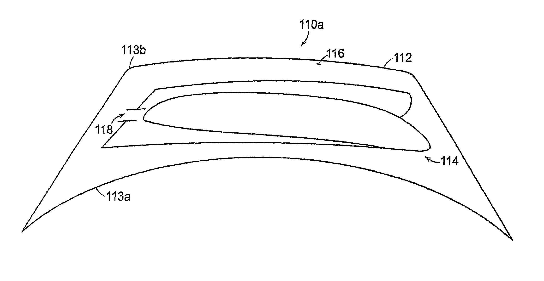
[0052]Referring now to the various figures of the drawing wherein like reference characters refer to like parts, there is shown in FIGS. 2A,B two embodiments according to the present invention of a scleral search coil assembly 110a,b, where FIG. 2A is an illustrative view of one embodiment and FIG. 2B is a schematic view of the other embodiment. In the following reference numeral 110 is used when referring to the scleral search coil assembly in general such as in the discussion concerning FIG. 3A. The scleral search coil assembly 110a illustrated in FIG. 2A includes a support member 112 and a resonating coil 114a that is disposed within the support member. The resonating coil 114a is arranged so that its plane is perpendicular to the line of sight. With such a coil arrangement, when the search coil assembly 110a is on the eye it should be possible to deduce the direction of gaze (horizontal and vertical position) with the appropriate number and placement of receiver coils as hereina...


PUM


Abstract

Featured is a wireless scleral search coil that includes one or more passive, resonant coils and in a particular embodiment two orthogonal, passive, resonant coils, where each coil resonates at a different frequency. Each resonant coil includes a coil-capacitor circuit, each circuit being configured to resonant at a different frequency. Such a wireless scleral search coil is disposed within a biocompatible material that is shaped to conform and rest upon the eye of a subject. Also featured are system including such a wireless scleral search coil, one or more transmitter coils, an assembly of one or more receiver coils and a calculating sub-system for processing signal data to obtain eye measurement information.

Description

[0001]This application claims the benefit of U.S. Provisional Application Ser. No. 60 / 682,731 filed May 19, 2005, the teachings of which are incorporated herein by reference.STATEMENT REGARDING FEDERALLY-SPONSORED RESEARCH[0002]The present invention was supported by grants from the National Science Foundation (NSF), grant number DBI-9876635 and the National Institute of Health (NIH / MIBIB), grant number R)1 EB001914. The U.S. Government may have certain rights to the present invention.FIELD OF INVENTION[0003]The present invention generally relates to devices, systems and methods for measurement of eye movement, more particularly to devices, systems and methods embodying a scleral search coil and yet more particularly to devices, systems and methods embodying a wireless scleral search coil.BACKGROUND OF THE INVENTION[0004]The control of eye movements represents one of the most basic and fundamental motor control systems of the human brain, combining information from both low-level mot...

Claims


Application Information

Patent Timeline
Patent Type & Authority Patents(United States)
IPC IPC(8): A61B3/14
CPCA61B3/113
Inventor SHELHAMER, MARK JOHNROBERTS, DALE CHARLES
Owner THE JOHN HOPKINS UNIV SCHOOL OF MEDICINE
Learn More