
Method for fabricating plasma reactor parts

a technology of plasma reactor and parts, applied in the direction of arc welding apparatus, chemical vapor deposition coating, metallic material coating process, etc., can solve the problems of alumina parts being susceptible to breakage, contamination and defects on the mask substrate, and deterioration due to contamination and defects

Active Publication Date: 2011-04-05
APPLIED MATERIALS INC
View PDF24 Cites 5 Cited by
  • Summary
  • Abstract
  • Description
  • Claims
  • Application Information

AI Technical Summary

Problems solved by technology

When chamber parts or process kits are exposed to the plasma environment for extended periods, deterioration may occur due to reaction with the plasma species.
It is believed that alumina is vulnerable to attack by fluorine species, resulting in the formation of AlxFyOz on the surface of component parts.
Such etch by-product may come off as particles during processing, resulting in contamination and defects on the mask substrate.
Furthermore, some alumina parts seem to be susceptible to breakage, probably as a result of mechanical stress created during machining.

Method used


Image

  • Method for fabricating plasma reactor parts
  • Method for fabricating plasma reactor parts
  • Method for fabricating plasma reactor parts

Examples


Embodiment Construction

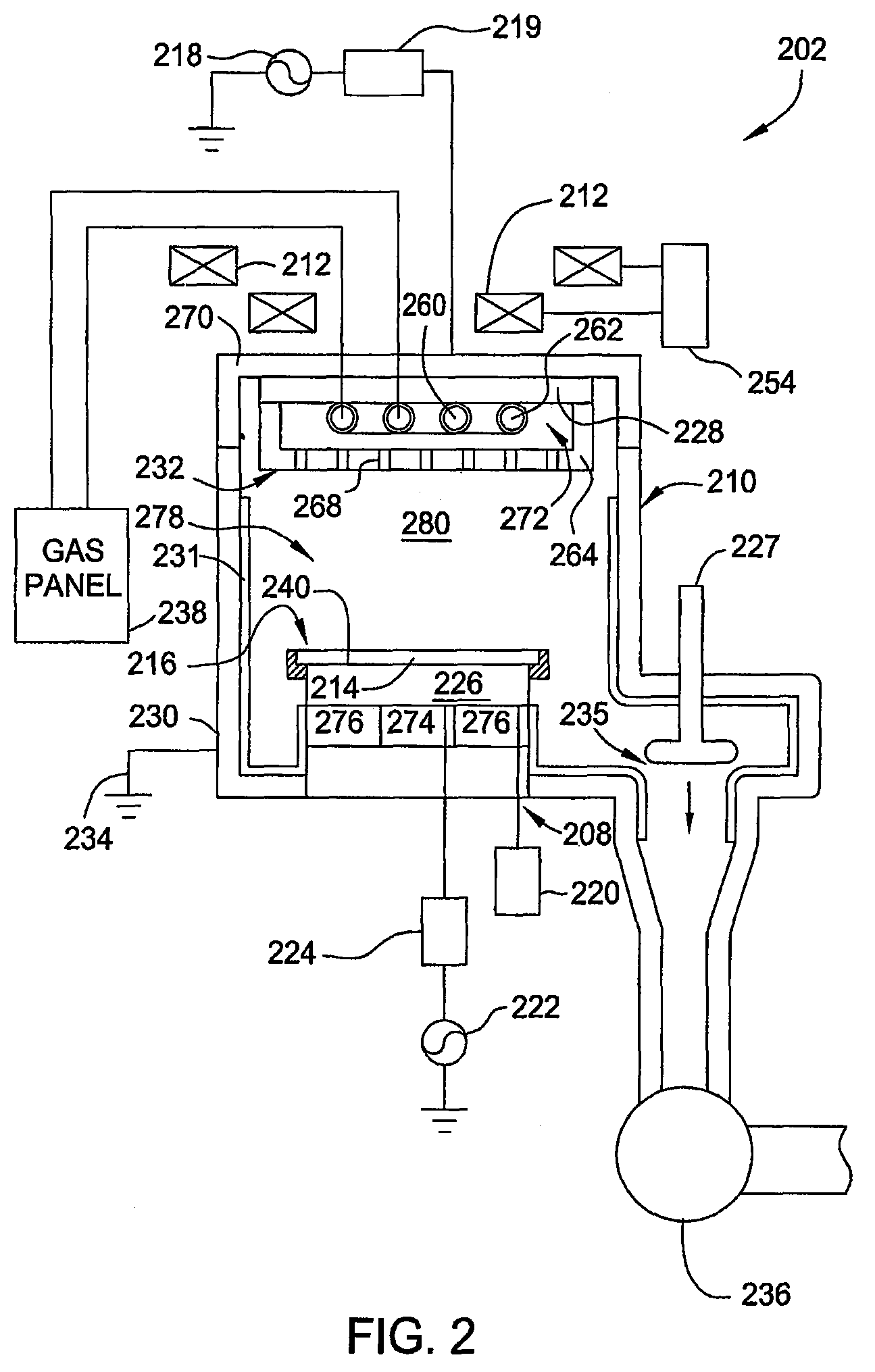
[0017]Certain embodiments of the present invention provide a method for fabricating parts made of bulk or solid yttria with improved characteristics such as reduced stress and enhanced chemical resistance. Certain other embodiments include chamber components made of bulk or solid yttria with improved characteristics, and processing chambers utilizing the same. Specifically, it is found that such improved characteristics are obtained if a part is subjected to a high temperature anneal after it is machined. Additionally, such characteristics may be further improved if the part is sintered or annealed in an oxygen containing environment.

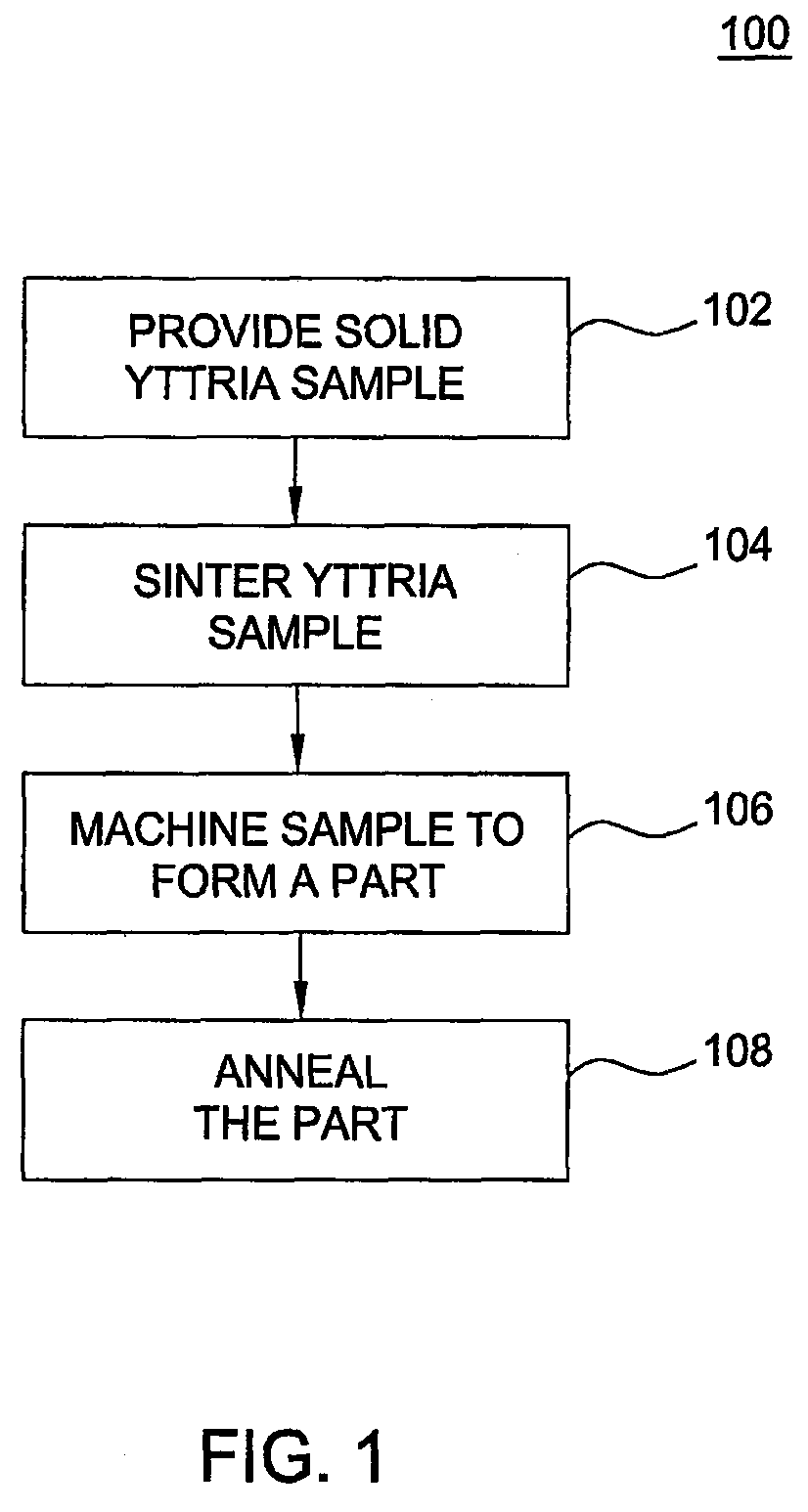
[0018]FIG. 1 illustrates one embodiment of a method 100 that can be used to fabricate these improved yttria parts. A solid yttria sample is provided at the beginning of the process in block 102 of the method 100. The solid yttria sample may be made by a variety of techniques known to one skilled in the art. For example, yttria (yttrium oxide, Y2O3) in p...


PUM

PropertyMeasurementUnit
temperatureaaaaaaaaaa

Abstract

A method of fabricating yttria parts is provided herein. In one embodiment, the method includes sintering a yttria sample, machining the sintered sample to form a part, and annealing the part by heating the part at a predetermined heating rate, maintaining the part at a constant annealing temperature, and cooling the part at a predetermined cooling rate. At least one of the sintering and annealing atmospheres is an oxygen-containing atmosphere.

Description

CROSS-REFERENCE TO RELATED APPLICATION[0001]This application is a continuation-in-part of U.S. patent application Ser. No. 11 / 554,482, entitled “Method and Apparatus for Photomask Etching”, filed on Oct. 30, 2006 (APPM / 11450), which is herein incorporated by reference in its entirety.BACKGROUND[0002]1. Field[0003]Embodiments of the present invention generally relate to a method and apparatus for plasma processing and, more specifically, to a method and apparatus for plasma processing with improved component parts.[0004]2. Description of the Related Art[0005]The fabrication of microelectronics or integrated circuit devices typically involves a complicated process sequence requiring hundreds of individual steps performed on semiconductors, dielectric and conductive substrates. Examples of these process steps include oxidation, diffusion, ion implantation, thin film deposition, cleaning, etching and lithography. Plasma processes are often used for thin film deposition and etching, whic...

Claims


Application Information

Patent Timeline
Patent Type & Authority Patents(United States)
IPC IPC(8): B23K10/00
CPCC04B35/505C04B35/64H01J37/32467Y10T29/49002C04B2235/663C04B2235/662G03F7/70908
Inventor RYABOVA, ELMIRASUN, JENNIFERYUAN, JIE
Owner APPLIED MATERIALS INC
Learn More