Cogeneration system for grease separation and power production

a technology of cogeneration system and grease, applied in the direction of centrifugal force sediment separation, energy-based wastewater treatment, machines/engines, etc., can solve the problems of not providing an economically useful method of fogging, forming glycerin which is not generally a useful product, and providing a means for economically recovering grease, etc., to achieve substantial cost advantages, reduce viscosity, and simple treatmen

Inactive Publication Date: 2009-12-29
TOOMBS ALVIN EDWIN
View PDF15 Cites 5 Cited by
  • Summary
  • Abstract
  • Description
  • Claims
  • Application Information

AI Technical Summary

Benefits of technology

[0018]d. The availability of engine waste heat allows for heating of the grease fuel to reduce its viscosity enough to be used as a diesel engine fuel.
[0019]The invention, a combined process for the recovery of a grease fuel from concentrated grease trap pumpings and production of electric power, embodies a method to overcome the limitations inherent in the use of recovered grease as a fuel for compression ignition engines and to use byproduct heat from the engine to provide the required process heat. The ability to utilize this fuel with a simple treatment—avoiding the cost of supplemental chemical treatment and the attendant byproduct disposal problem—by making use of the waste heat from the engine generator offers substantial cost advantages in dealing with this common waste stream.
[0020]Brown Grease in particular is a difficult waste stream to process. It is normally encountered in the form of a grease trap pumpings consisting of about 1-5% FOG materials (fats, oils and grease), with the remainder being water plus a variety of particulate residue (mostly dirt and solid food particles). The grease content in the pumping stream makes treatment at conventional water treatment facilities very difficult. The two stage heated separation process with the resulting grease fuel being used directly in a compression ignition engine is a simple, straightforward means of dealing with this problematic waste stream. The grease is completely incinerated in the engine and produces a beneficial byproduct (electricity) instead of a difficult and expensive disposal problem.
[0021]For the purposes of this invention, the grease trap pumpings have been pretreated in a water treatment plant to produce concentrated grease slurry that has had from about 40-80% of the water removed. This volumetric reduction is an ordinary practice in the water treatment industry today generally accomplished by simple gravity separation in a holding tank.
[0022]The invention consists of adding the concentrated grease trap pumpings to a grease slurry process tank where engine waste heat is used to warm the contents to liquefy all contained grease. The materials in this tank are mixed during the heating process and then passed through a centrifuge in order to separate the mixture into two parts. The heavy portion contains water and sediments that are sent to a water treatment plant for normal processing. The lighter portion (oil-rich stream) contains oil, oil / water emulsion and some residual water. This portion is sent to a grease fuel dewatering tank in which the material is heated to a temperature sufficient to evaporate all the contained water leaving a grease fuel that is suitable for use in a compression ignition engine.
[0023]Other than the care needed for startup and shutdown to allow for adequate heat-up of the grease fuel stream in the former and purging of the grease fuel in the later, operation of the engine generator set is similar to an engine operating with conventional diesel fuel.

Problems solved by technology

U.S. Pat. Nos. 3,769,207 and 5,637,221 both present processes to separate emulsified and greasy materials from a wastewater stream while U.S. Pat. No. 4,113,617 presents an improved grease trap design but none of these provide a means for economically recovering the grease.
The later three cases also fail to provide an economically useful method of utilizing the FOG.
In general, prior art has focused on eliminating the FOG as a problem in the waste water treatment process and not on the potential economic value of the grease.
It requires the use of supplemental chemicals and results in the formation of glycerin which is not generally a useful product.
However, this invention will allow for the direct use of the grease fuel in a diesel engine without the use of supplemental chemicals and will not produce additional byproduct wastes.
Brown Grease in particular is a difficult waste stream to process.
The grease content in the pumping stream makes treatment at conventional water treatment facilities very difficult.
The grease is completely incinerated in the engine and produces a beneficial byproduct (electricity) instead of a difficult and expensive disposal problem.

Method used


Image

  • Cogeneration system for grease separation and power production
  • Cogeneration system for grease separation and power production

Examples


Embodiment Construction

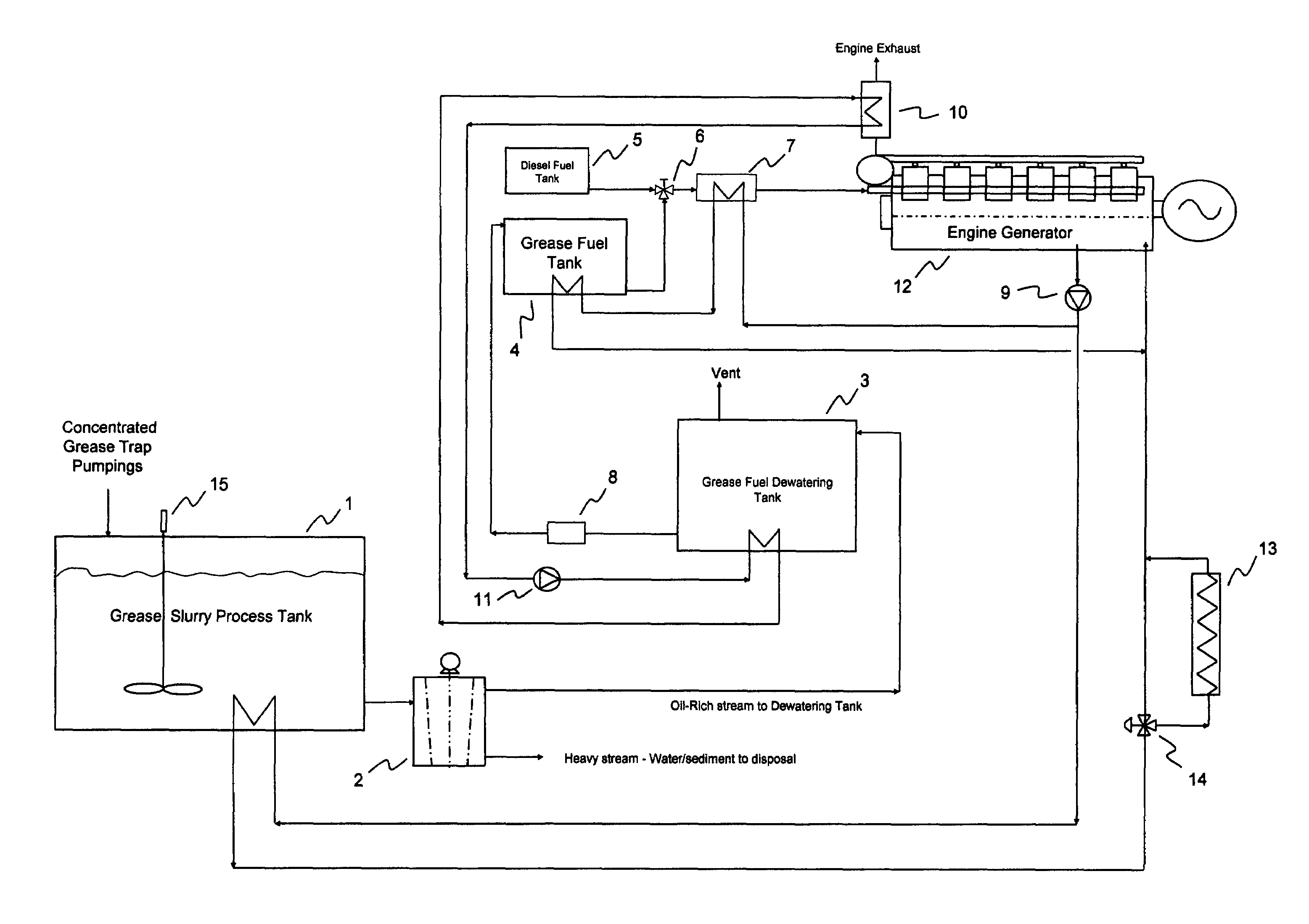
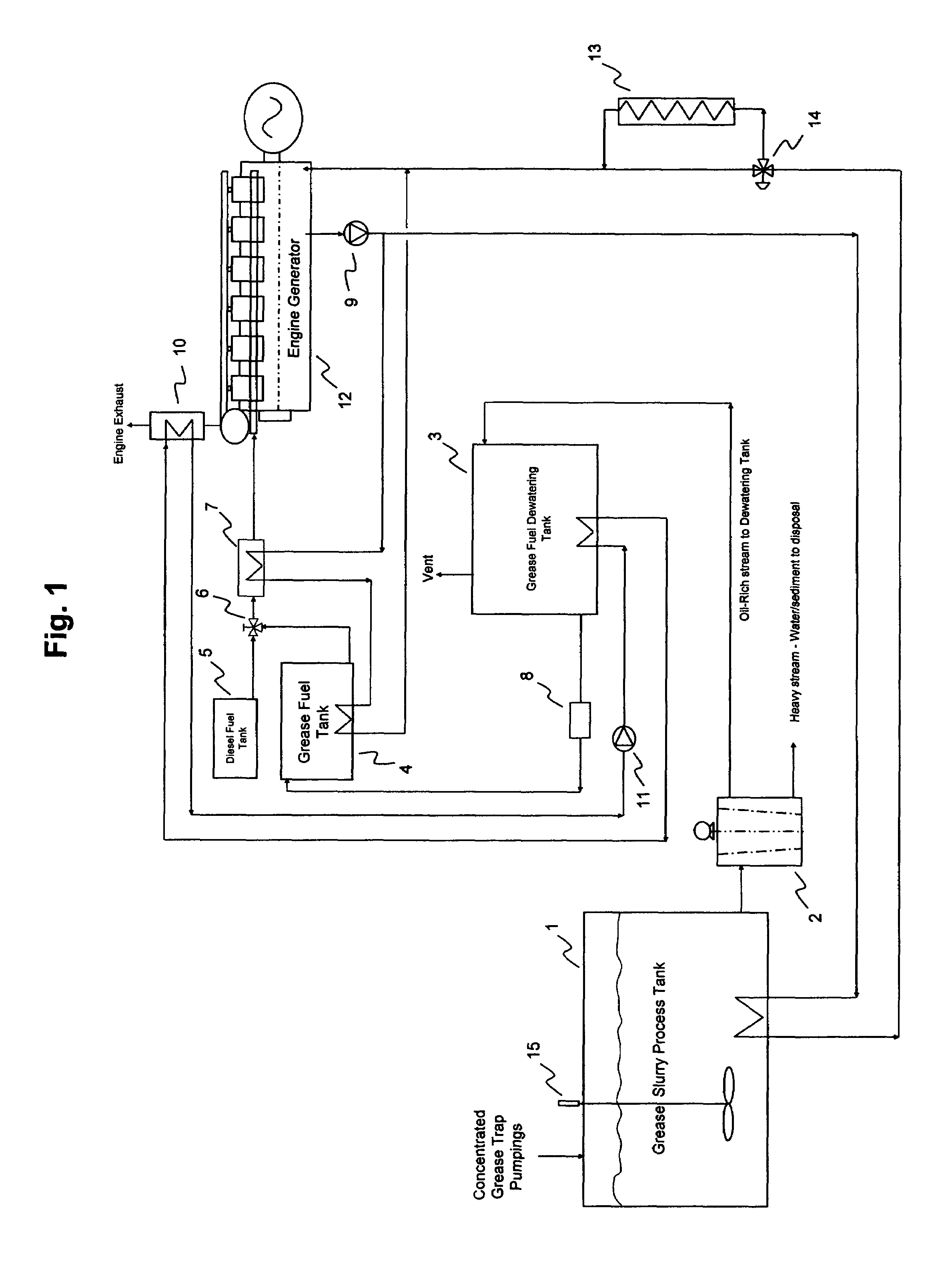
[0040]FIG. 1 is a process flow diagram of the preferred embodiment of the invention: a cogeneration system for a grease separation and power production. Concentrated grease trap pumpings are added to a grease slurry process tank (1) where heat is added to the tank contents from the engine jacket water heating loop until the temperature of the tank's contents is sufficient to liquefy all grease matter. The tank contents are kept homogeneous by a mixer (15). Tank contents are drawn from the tank and sent to a centrifuge (2) in which process flow is split into a heavy stream containing water and sedimentary particles and a light stream containing oil, oil / water emulsion and some residual water. The heavy stream is sent to a conventional wastewater treatment system for disposal. The light (oil-rich) stream is sent to a grease fuel dewatering tank (3) where it is heated to a temperature greater than the boiling point of water by a process heating loop circulating a high temperature heat ...


PUM

PropertyMeasurementUnit
electric poweraaaaaaaaaa
heat exchangeaaaaaaaaaa
temperatureaaaaaaaaaa

Abstract

A cogeneration process and system which provides for the reclamation of a grease fuel from a concentrated grease trap pumping waste stream and the use of said grease fuel in a compression ignition reciprocating engine for the production of electric power. The concentrated grease trap pumpings are heated and mixed in the first stage of the process to ensure all grease is liquefied. This warm mixed stream is then separated by centrifuge into a heavy stream consisting of water and sediments and an oil-rich stream consisting of oil, grease/water emulsion and residual water. This oil-rich mixture is heated sufficiently to evaporate the residual water as well as the water of emulsion yielding a water free grease fuel suitable for use in the compression ignition engine. Heat energy for grease liquefaction and emulsion breaking is supplied by an engine jacket water cooling circuit and an exhaust heat recovery, respectively.

Description

CROSS REFERENCE TO RELATED APPLICATION[0001]NoneFEDERALLY SPONSORED RESEARCH[0002]NoneSEQUENCE LISTING[0003]NoneFIELD OF THE INVENTION[0004]This invention relates to a cogeneration system for recovering grease from a waste water stream and producing electric power and process heat with a reciprocating engine generator using the recovered grease as fuel.BACKGROUND OF THE INVENTION[0005]The wastewaters produced from restaurants and other large scale food processing facilities inherently contain large amounts of fats, oils and greases (this is often referred to as FOG and the general waste stream is often referred to as Brown Grease). Wastewater discharges from such facilities must be via a grease trap prior to release to public waste water streams. These grease traps are essentially crude gravity separation devices that prevent carryover of FOG to the public sewer. These traps work reasonably well provided that they are pumped out regularly. This pumping is typically performed using a...

Claims


Application Information

Patent Timeline
Patent Type & Authority Patents(United States)
IPC IPC(8): C02F1/02F02C3/00
CPCF02M25/0228F02D19/0657C10L1/08C02F1/048C02F2101/32C02F2103/32C02F2303/10Y02T10/36F02D41/0027Y02T10/121Y02T10/12Y02T10/30Y02W10/30
Inventor TOOMBS, ALVIN EDWIN
Owner TOOMBS ALVIN EDWIN
Why Eureka
Try Eureka