
Metal component for fuel cell and method of manufacturing the same, austenitic stainless steel for polymer electrolyte fuel cell and metal component for fuel cell material and method of manufacturing the same, corrosion-resistant conductive component and method of manufacturing the same, and fuel cell

a technology of austenitic stainless steel and fuel cells, which is applied in the direction of cell components, final product manufacturing, sustainable manufacturing/processing, etc., can solve the problems of undesired exposure in certain parts, and achieve excellent corrosion resistance, suppress surface roughness, and excellent corrosion resistance

Inactive Publication Date: 2009-10-06
DAIDO STEEL CO LTD
View PDF19 Cites 2 Cited by
  • Summary
  • Abstract
  • Description
  • Claims
  • Application Information

AI Technical Summary

Benefits of technology

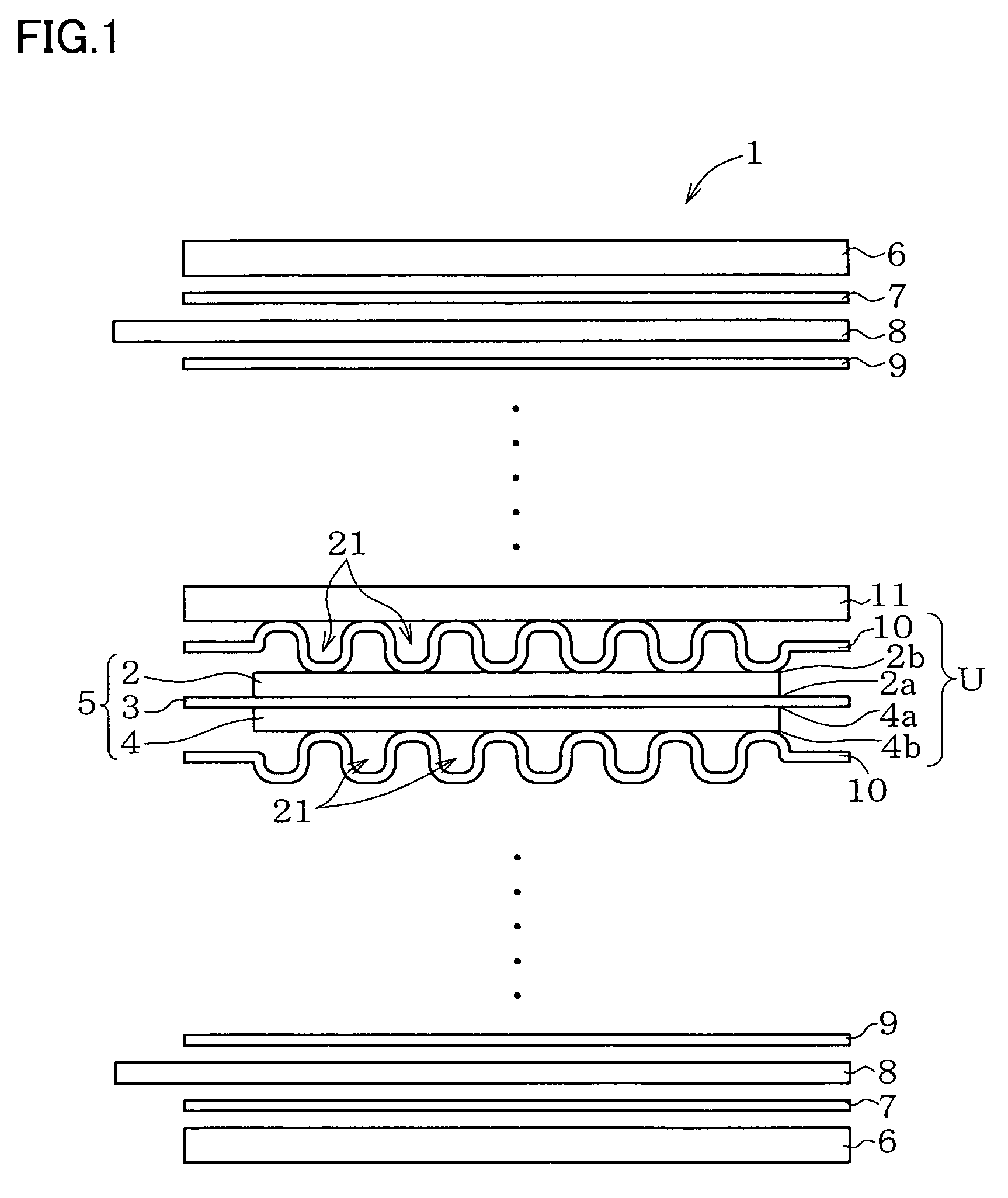
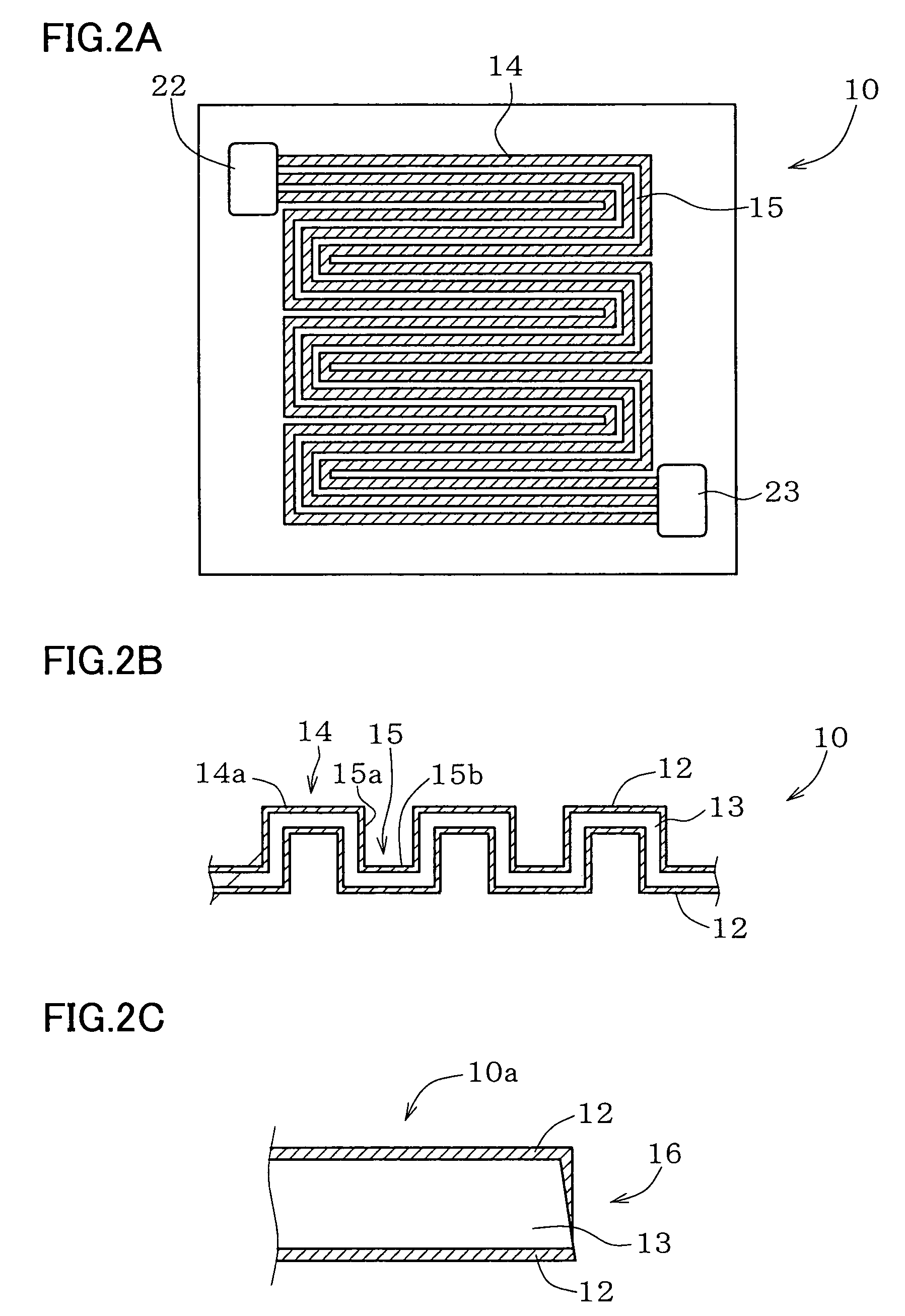
[0041]The present inventors therefore made an experiment as described below. SUS316L was used as a material for composing the metal base, which is processed into the separator, an Au film of 100 nm thick or around was formed on the surface of the metal base before the metal base is shaped into the separator geometry, and the metal base is then dipped into a corrosive solution. The end face of the separator formed a cutting plane, and had some region where the metal base exposes therein. The corrosive solution was a sulfuric acid solution of pH2, had a temperature of 100° C., and dipping time was set to 168 hours. The cutting plane of the metal base after the experiment was observed. No change in color of the metal base was observed even it was exposed in the cutting plane, and therefore no corrosion of the metal base was observed. The result indicates that the exposed region of the metal component disposed in contact with the main unit of fuel cell is not always corroded, even if the surface thereof is exposed to the corrosive environment, provided that the Au film resides in the neighboring region. The present inventors found out, as demonstrated by the above-described experiment, that a metal component for fuel cell having a satisfactory corrosion resistance can be obtained even if the metal base is cut after the Au film is formed thereon, and the fact led us to the first invention. Adoption of this method typically makes it possible to form the Au film en bloc over a region of a relatively wide range, such as over the surface of a band-formed metal base, and thereby makes it possible to simplify a process of formation of the Au film. In thus-manufactured metal component for fuel cell of the first invention, a desirable corrosion resistance can be ensured even if the metal base exposes in the region to be brought into direct contact with the electrode, or the region to be brought into direct contact with a corrosive environment such as a moisture-containing oxidizer gas (air, for example) atmosphere, so that it is no more necessary to roller-press the Au film after formation thereof, or to form the Au film to a relatively large thickness (1 μm or around, for example), in order to suppress formation of the pinholes. This makes it possible to further facilitate the manufacturing, reduces Au consumption, and to realize an inexpensive metal component for fuel cell. It was also found that corrosion of the metal base can sufficiently be suppressed if the width of the surface of the metal base, exposed in the cutting plane of the metal component, is as wide as 1 mm or less. The width of the exposed surface of the metal base exceeding 1 mm makes the exposed region of the metal base in the cutting plane too wide, and is unsuccessful in realizing a sufficient level of corrosion resistance in the cutting plane.
[0094]Use of the austenitic stainless steel for the base allows Fe, Cr and Ni, which are major components thereof, to appear in the intermediate layer between the base and noble metal layer, and even in the noble metal layer. It was made clear that ratio of contents of these elements, thus appear in the noble metal layer and in the intermediate layer, is particularly important for the corrosion resistance. More specifically, the noble metal layer and the intermediate layer preferably have a maximum Cr / Fe ratio of 3 or less, and a maximum Ni / Fe ratio of 2 or less. This is also supported by data described below.

Problems solved by technology

That is, shaping of the metal base having the Au film formed thereon may cause crack in the Au film already formed thereon, or produce a cutting plane by cutting of the metal base, to thereby allow the metal base to expose in these regions, and corrosion is supposed to proceed in thus-exposed metal base.
In fact, the aforementioned patent publication discusses that the pinholes formed in the Au plated film are regions where the metal base exposes and the corrosion thereof can proceed, so that this sort of exposure must be undesired.

Method used


Image

  • Metal component for fuel cell and method of manufacturing the same, austenitic stainless steel for polymer electrolyte fuel cell and metal component for fuel cell material and method of manufacturing the same, corrosion-resistant conductive component and method of manufacturing the same, and fuel cell
  • Metal component for fuel cell and method of manufacturing the same, austenitic stainless steel for polymer electrolyte fuel cell and metal component for fuel cell material and method of manufacturing the same, corrosion-resistant conductive component and method of manufacturing the same, and fuel cell
  • Metal component for fuel cell and method of manufacturing the same, austenitic stainless steel for polymer electrolyte fuel cell and metal component for fuel cell material and method of manufacturing the same, corrosion-resistant conductive component and method of manufacturing the same, and fuel cell

Examples


example 1

[0165]The second inventive examples and comparative example Steels (SUS304-base) having compositions shown in Table 3 below were melted and forged to thereby prepare ingots, and the ingots were further forged and rolled to thereby manufacture steel plates of 0.2 mm thick. The steel plates were then subjected to solution treatment at 1,100° C., and punched to produce 50×40 mm test pieces for the corrosion test. The test pieces were then subjected to the corrosion test by the procedures described below. Results are shown in Table 3. In the corrosion test, the above-described test piece was kept as being dipped in 0.4 liter (L) of a 0.1 wt % sulfuric acid solution (approximately pH2) boiled under reflux for 168 hours, and metal ions eluted into the solution was analyzed by atomic absorption spectrometry, and amount thereof was expressed in weight per 0.4 liter (L) of the solution.

[0166]

TABLE 3Amount of ion elutionComposition (wt %)(mg / 0.4 liter)Judg-No.CSiMnPSCuNiCrMo*NNbA**FeCrNiCuMom...

example 2

[0169]The second inventive examples and comparative example steels (SUSXM7-base) having compositions shown in Table 4 below were processed similarly to as described in Example 1, to thereby manufacture 50×40 mm sample steel plates for corrosion-resistant of 0.2 mm thick. The test pieces were then subjected to the corrosion test by the procedures described in the above. Results are shown in Table 4.

[0170]

TABLE 4Amount of ion elutionComposition (wt %)(mg / 0.4 liter)Judg-No.CSiMnPSCuNiCrMo*NTiA**FeCrNiCuMomentInventive140.0580.480.680.0110.0042.168.0517.090.500.0200—19.05.41.20.6◯Examples150.0560.480.650.0120.0042.128.0817.101.010.0210—18.44.61.10.5◯160.0660.380.780.0280.0063.8410.1218.952.060.0060—22.25.21.50.8◯170.0680.350.770.0270.0063.829.7818.753.040.0050—22.76.82.01.10.20.3◯180.0620.380.770.0280.0053.869.4618.444.000.0070—21.19.92.91.60.40.6◯190.0180.240.260.0160.0043.5510.1118.652.100.0130—7.01.80.50.3◯200.0080.150.020.0050.0023.6210.1618.702.130.0120—2.60.60.20.1◯210.0630.320.76...

example 3

[0173]The second inventive examples and comparative example Steels (SUS316-base) having compositions shown in Table 5 below were processed similarly to as described in Example 1, to thereby manufacture 50×40 mm sample steel plates for corrosion-resistant of 0.2 mm thick. The test pieces were then subjected to the corrosion test by the procedures described in the above. Results are shown in Table 5.

[0174]

TABLE 5Amount of ion elutionComposition (wt %)(mg / 0.4 liter)Judg-No.CSiMnPSCuNiCrMo*NNbA**FeCrNiCuMomentInventive220.0650.650.740.0300.0090.1110.5616.332.220.0290—22.5102.21.40.3◯Examples230.0220.730.970.0250.0060.5012.2217.562.120.0150—12.21.00.20.2◯240.0200.720.960.0240.0051.0012.3217.542.100.0160—11.40.80.20.1◯250.0550.440.680.0300.0072.0213.6618.021.320.0070—19.31.10.30.2◯260.0540.460.660.0280.0074.0313.5618.001.350.0080—18.92.00.60.4◯270.0680.720.470.0160.0056.0014.3218.413.580.0210—21.05.01.51.20.50.3◯280.0200.260.270.0230.0022.0313.8618.101.590.0110—7.30.60.20.1◯290.0090.150.0...


PUM

PropertyMeasurementUnit
widthaaaaaaaaaa
surface roughnessaaaaaaaaaa
thickaaaaaaaaaa

Abstract

An Au plated film 12 is formed on the surface of a plate-formed metal base 13 composed of a metal less noble than Au, and the product is cut along a planned cutting line 18 reflecting a contour of a desired component, to thereby form a separator 10. Thus-formed separator 10 has the Au plated film 12 formed on the main surface 10a thereof, and has a cutting plane 16 formed as an end face 16 stretched up to the main surface 10a. The metal base 13 exposes in a part of the cutting plane 16, in a width of the exposed region of 1 mm or less. This is successful in providing a metal component for fuel cell which is satisfactory in the corrosion resistance and allows easy fabrication at low costs, a method of manufacturing the same, and also in providing a fuel cell having thus-fabricated metal component for fuel cell.

Description

TECHNICAL FIELD[0001]A first invention relates to a metal component for fuel cell and a method of manufacturing the same, and also to a fuel cell.[0002]A second invention relates to an austenitic stainless steel for polymer electrolyte fuel cell, and more specifically to an austenitic stainless steel for polymer electrolyte fuel cell used for conductive separator, current collector and so forth, and a metal component for fuel cell using the same, and also to a fuel cell.[0003]A third invention relates to a polymer electrolyte fuel cell material such as a metal separator, current collector plate and so forth used in polymer electrolyte fuel cell, and a method of manufacturing the same, and also to a metal component for fuel cell using the same and a fuel cell.[0004]A fourth invention relates to a corrosion-resistant conductive material represented by a metal separator for fuel cell, and a method of manufacturing the same, and also to a fuel cell.BACKGROUND ART(First Invention)[0005]T...

Claims


Application Information

Patent Timeline
Patent Type & Authority Patents(United States)
IPC IPC(8): H01M8/02B32B15/01B32B15/18H01M50/571
CPCH01M8/0206H01M8/021H01M8/0228H01M8/0254H01M2008/1095Y10T428/12951Y10T428/12944Y10T428/12993Y10T428/12896Y10T428/12889Y10T428/12875Y02E60/50Y02P70/50
Inventor TAKAGI, SHINOBUSHINKAWA, MASAKIURA, MIKIOYAGI, SHINICHIKANETA, YASUSHIHISADA, TATSUO
Owner DAIDO STEEL CO LTD
Learn More