Electrode for lithium batteries and rechargeable lithium battery
- Summary
- Abstract
- Description
- Claims
- Application Information
AI Technical Summary
Benefits of technology
Problems solved by technology
Method used
Image
Examples
reference experiment 1
Fabrication of Negative Electrode
[0101]A microcrystalline silicon thin film was formed on a rolled copper foil (18 μm thick) by a CVD method, using the rolled copper foil as a substrate, silane (SiH4) as a source gas and a hydrogen gas as a carrier gas. Specifically, the copper foil as a substrate was placed on a heater within a reaction chamber. An interior of the reaction chamber was evacuated by a vacuum evacuator to a pressure of 1 Pa or lower. The silane gas as a source gas and the hydrogen (H2) gas as a carrier gas were introduced via a source gas inlet port. The substrate was heated to 180° C. on the heater. A degree of vacuum was adjusted by the vacuum pumping apparatus to a reaction pressure. An RF power supply was operated to excite a radio frequency wave which is introduced via an electrode to induce a glow discharge. Detailed thin-film forming conditions are listed in Table 1. In Table 1, a volumetric unit, sccm, indicates a volumetric flow rate (cm3 / minute) of a fluid a...
reference experiment 2
[0120]The procedure used in Reference Experiment 1 to construct the battery A1 was followed, except that an electrolytic copper foil (18 μm thick) was used for the current collector as a substrate. That is, a microcrystalline silicon thin film (about 10 μm thick) was deposited on the electrolytic copper foil to fabricate an electrode a3. Using this electrode, a battery A3 was constructed.
[0121]Also, the rolled copper foil used in Reference Experiment 1 was subjected to a one-minute grinding treatment with a #400 or #120 emery paper to provide a ground copper foil. The procedure used in Reference Experiment 1 to construct the battery A1 was followed, except that such a ground copper foil was used for the current collector as a substrate. That is, a microcrystalline silicon thin film (about 10 μm thick) was deposited on the copper foil to fabricate an electrode. The electrode fabricated using the copper foil ground with a #400 emery paper was designated as an electrode a4 and the elec...
reference experiment 3
[0126]The batteries A1 and A3 respectively constructed in Reference Experiments 1 and 2 were further subjected to a charge-discharge cycle test under the same test conditions as used in the Reference Experiment 1 to measure a 30th-cycle capacity retention rate. The results are shown in Table 4.
[0127]
TABLE 4Battery30th-Cycle Capacity Retention RateA191%A397%
[0128]As can be clearly seen from the results given in Table 4, the batteries A1 and A3 exhibit good capacity retention rates even on the 30th-cycle. Particularly, the battery A3 using the copper foil with a higher value of surface roughness Ra for the current collector exhibits good capacity retention rate.
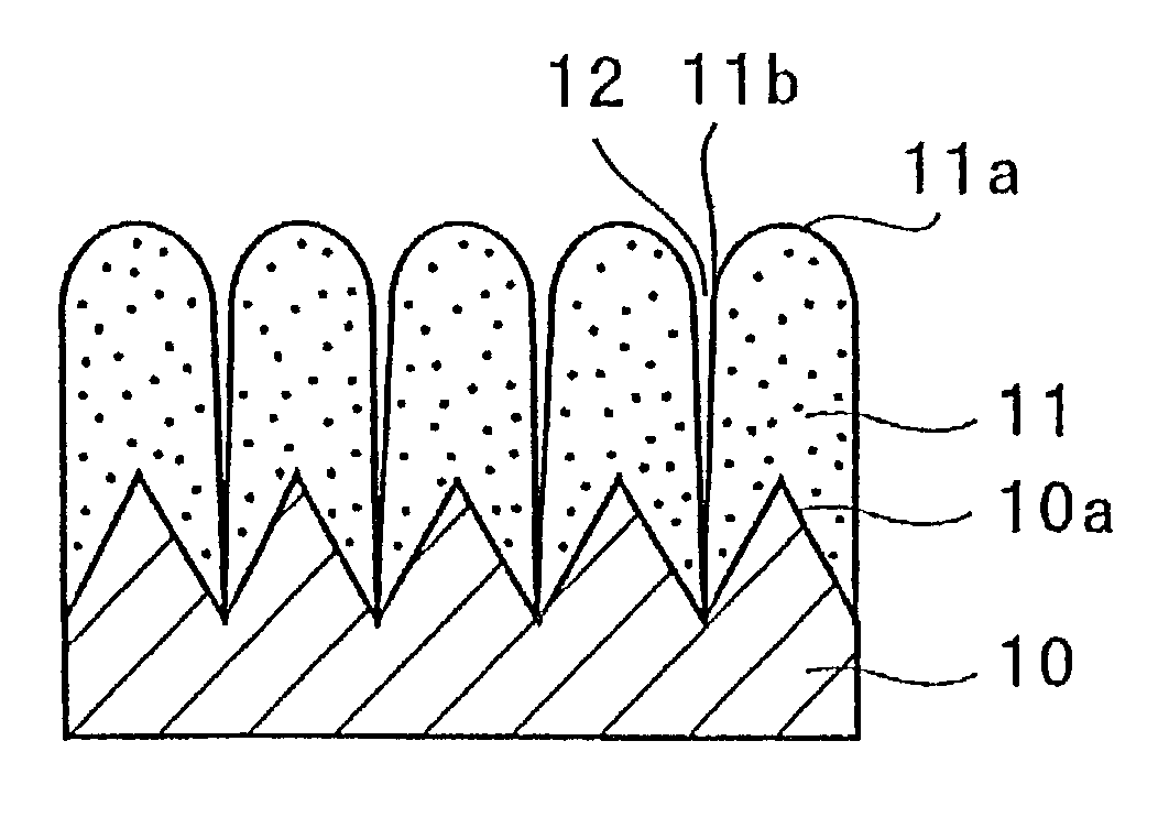
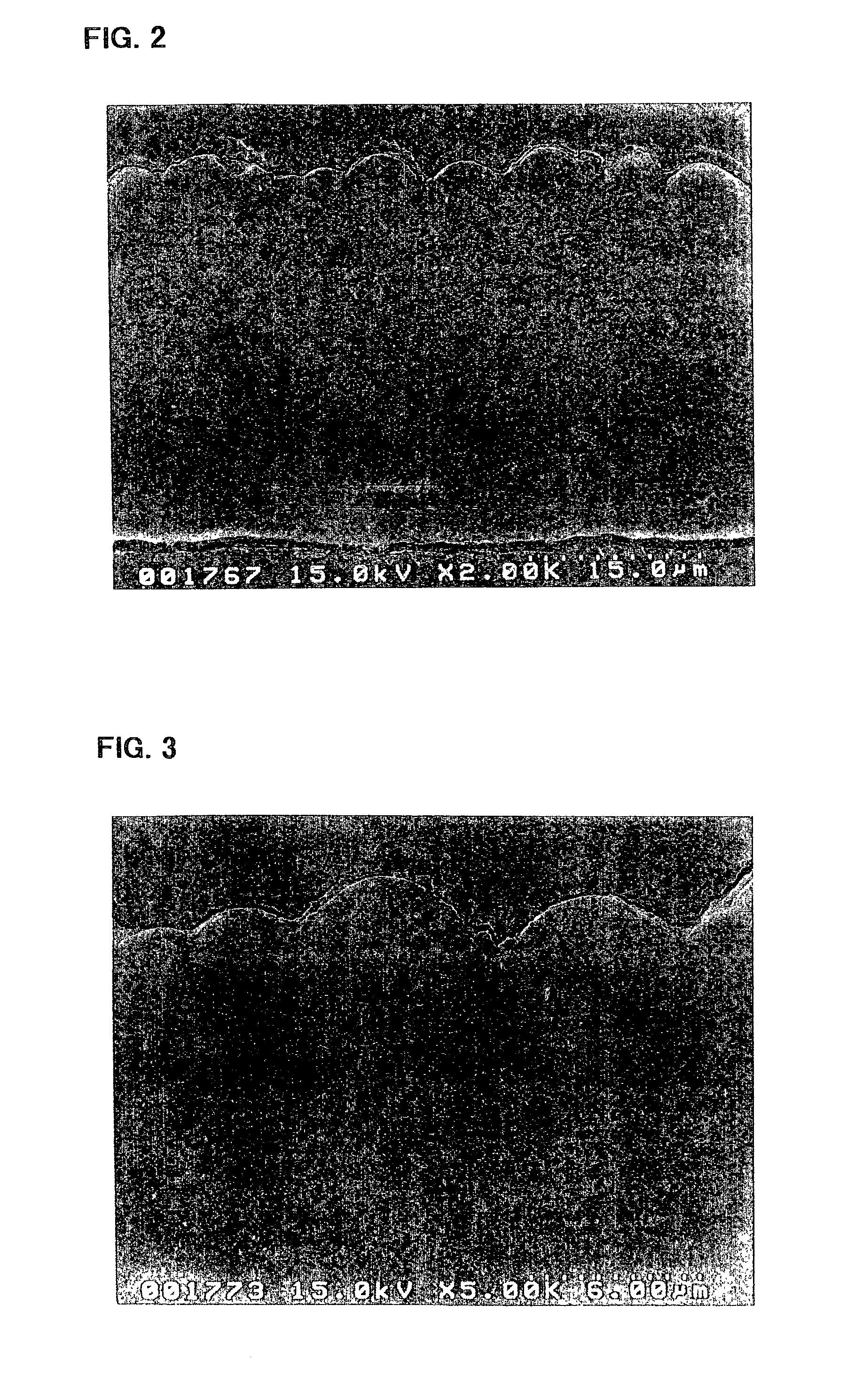
[0129]The electrode a3 incorporated in the battery A3 was viewed under an electron microscope to observe a condition of its silicon thin film. First, the electrode a3 in its state prior to being incorporated in the battery, i.e., before charge and discharge, was observed using a scanning electron microscope. FIGS. 2 and 3 are p...
PUM
 Abstract
Description
Claims
Application Information
 - R&D
- Intellectual Property
- Life Sciences
- Materials
- Tech Scout
- Unparalleled Data Quality
- Higher Quality Content
- 60% Fewer Hallucinations
Browse by: Latest US Patents, China's latest patents, Technical Efficacy Thesaurus, Application Domain, Technology Topic, Popular Technical Reports.
© 2025 PatSnap. All rights reserved.Legal|Privacy policy|Modern Slavery Act Transparency Statement|Sitemap|About US| Contact US: help@patsnap.com


