Magnetic tunnel magneto-resistance device and magnetic memory using the same
a technology of magnetoresistance device and magnetic memory, which is applied in the direction of magnetic bodies, instruments, record information storage, etc., can solve the problems of deterioration of element characteristics, extremely weak magnetic coupling, and limited device structure and manufacturing processes, so as to improve the thermal resistance of a tmr device, high thermal reliability, and high density
- Summary
- Abstract
- Description
- Claims
- Application Information
AI Technical Summary
Benefits of technology
Problems solved by technology
Method used
Image
Examples
experiment 1
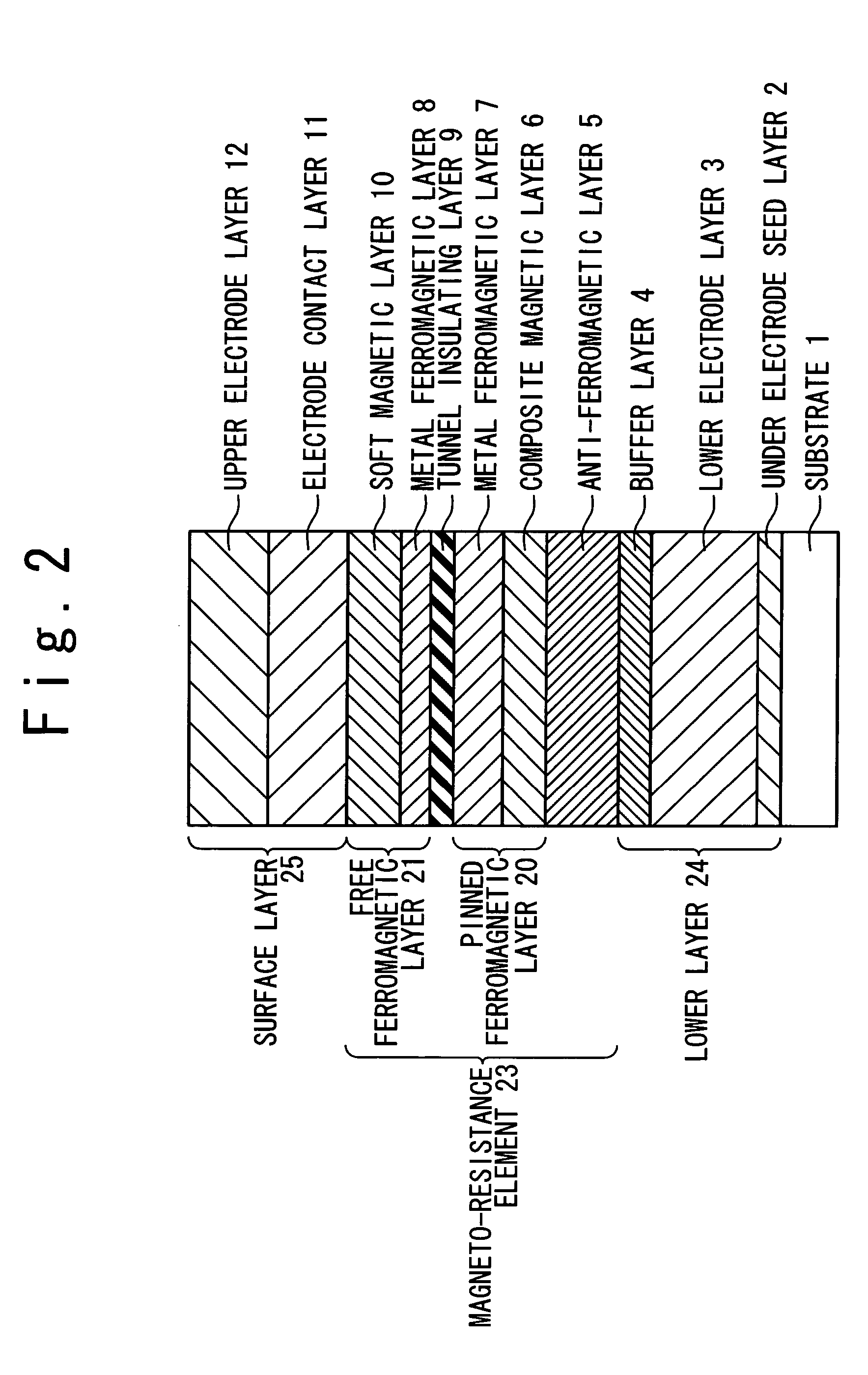
[0123]The magneto-resistance device of the present invention having the above-mentioned configuration was manufactured by the above-mentioned method. The result of the experiment shows improvement of the thermal stability and the like due to the introduction of the composite magnetic film. That will be described below with reference to FIG. 15.
[0124]FIG. 15 is graphs showing the relation between thermal treatment temperature and MR ratio in the magneto-resistance device. The vertical axis shows the MR ratio (%), and the horizontal axis shows the thermal treatment temperatures (° C.). Here, each of samples will be described below.
(5) Sample 5 (Comparison Example to the Conventional Example)
[0125]Substrate / Ta (3 nm) / Cu (50 nm) / Ta (15 nm) / Co90Fe10 (3 nm) / Pt49Mn51 (30 nm) / Co90Fe10 (9 nm) / Al (2 nm)-Ox / Co90Fe10 (2. nm) / Ni81Fe19 (7.5 nm) / Ta (30 nm) / Cu (300 nm).
[0126]Here, the sample is formed in the order of substrate / lower electrode seed layer / lower electrode layer / buffer layer / anti-ferro...
experiment 2
[0136]The magneto-resistance device is manufactured by the same method as the experiment example 1 to contain the CoFeAlOx composite magnetic layer 6 in the pinned ferromagnetic layer 20. The film structure will be described below with reference to FIG. 17.
[0137]FIG. 17 is a table showing relation between MR ratio and exchange coupling magnetic field. Here, each of samples is as follows.
experiment 3
[0148]The experimental example 3 of the anti-ferromagnetic coupling film using the composite magnetic layer will be described. The samples were manufactured, in which the Co90Fe10 (6 nm) metal ferromagnetic layer and the CoFeTaOx (5 nm) composite magnetic layer are ferromagnetically or anti-ferromagnetically coupled. The composite magnetic layer CoFeTaOx (6 nm) was formed by the reactive sputtering (the oxygen / argon flow rate ratio=0.13) by using the alloy target of (Co90Fe10)85Ta15 in a mixture atmosphere of argon and oxygen, and was the same film as the experiment example 1. After the film growth, thermal treatment at 300° C. was carried out on the sample in the magnetic field to give the magnetic anisotropy. Those magnetization curves (vibratory magnetometer) are described with reference to FIG. 18.
[0149]FIG. 18 is a graph showing magnetization curve of each of the samples. The vertical axis shows magnetization (emu) and the horizontal axis shows magnetic field (Oe). Here, each s...
PUM
| Property | Measurement | Unit |
|---|---|---|
| thickness | aaaaa | aaaaa |
| average grain diameter | aaaaa | aaaaa |
| temperature | aaaaa | aaaaa |
Abstract
Description
Claims
Application Information
 - R&D
- Intellectual Property
- Life Sciences
- Materials
- Tech Scout
- Unparalleled Data Quality
- Higher Quality Content
- 60% Fewer Hallucinations
Browse by: Latest US Patents, China's latest patents, Technical Efficacy Thesaurus, Application Domain, Technology Topic, Popular Technical Reports.
© 2025 PatSnap. All rights reserved.Legal|Privacy policy|Modern Slavery Act Transparency Statement|Sitemap|About US| Contact US: help@patsnap.com


