
Cast pedestal with heating element and coaxial heat exchanger

a technology which is applied in the field of coaxial heat exchanger and heating element cast pedestal, can solve the problems of further mechanical properties, inability to harden or strengthen the film, and softer and mechanically weaker than dense osg films, etc., and achieves heat resistance and high temperature gradient

Active Publication Date: 2008-02-05
NOVELLUS SYSTEMS
View PDF5 Cites 433 Cited by
  • Summary
  • Abstract
  • Description
  • Claims
  • Application Information

AI Technical Summary

Benefits of technology

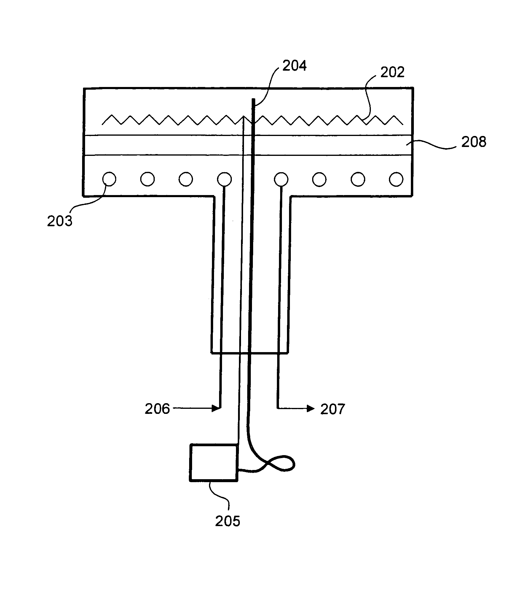
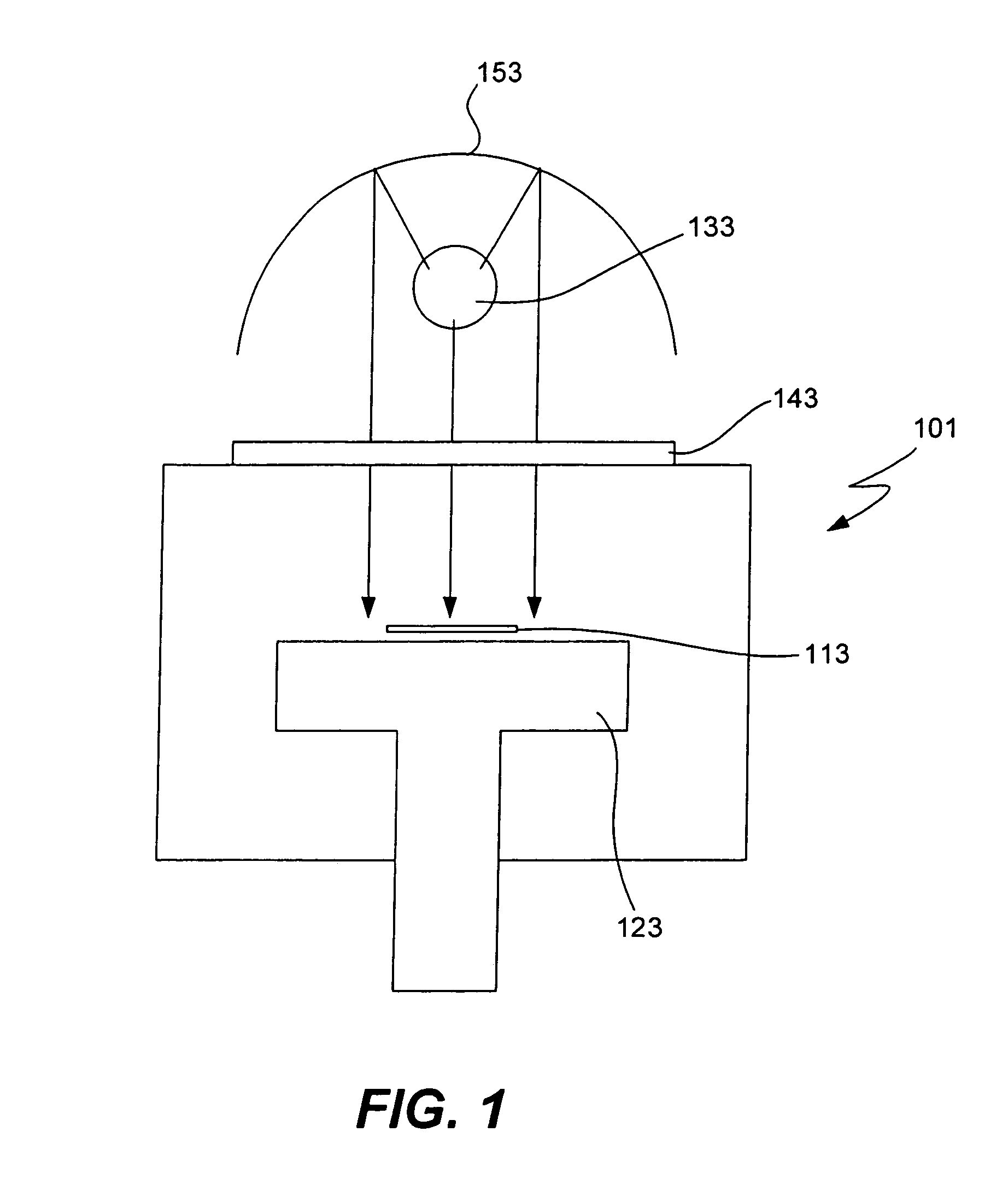
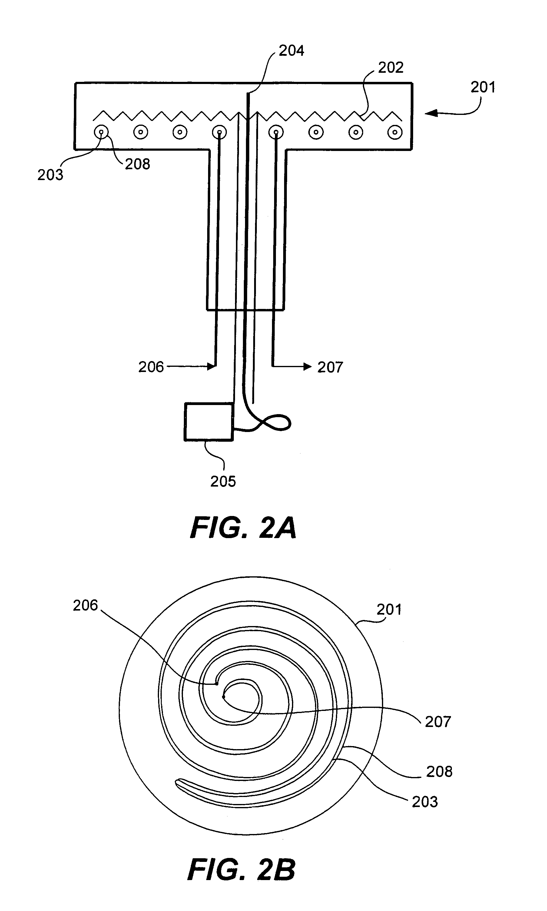
[0008]The present invention addresses these needs by providing a heat transfer assembly that, when coupled to an object, is capable of keeping the object at a uniform elevated temperature while removing large amounts of heat from an external source. Additionally, commonly available semiconductor fabrication facility water may be used as the only coolant. The assembly may be contained in a pedestal for use in a UV-cure chamber. The heat transfer assembly includes a heating element to control the wafer temperature and a cooling element to remove incident IR heat from the wafer and pedestal. A heat resistant layer having a calibrated heat resistance is located between the heating and cooling elements and between the wafer and the cooling elements. The heat resistant layer is able to sustain high temperature gradient from the wafer to the coolant so that the coolant does not boil while permitting enough heat to be conducted away from the wafer to maintain the desired set-point temperature. In some embodiments the heat transfer assembly includes coaxial tubes with coolant flowing through the inner tube and resistance materials in the annular gap between the tubes. The resistance materials may include a spiral coil and / or insulating material such as sand. In some embodiments, a compressed gas is included. The heat resistance may be calibrated by varying the pitch of the spiral coil, the annular gap distance, the materials in the layer and / or gas composition and pressure.

Problems solved by technology

However, the inclusion of pores in these films renders them softer and mechanically weaker than dense OSG films.
Thermal curing has no further effect on the mechanical properties of the film after the porogen has been driven out, and therefore cannot be used to harden or strengthen the film.
Curing with commercially available mercury-vapor UV lamps often results in areas of non-uniformity on the wafer because the tubular geometry of these lamps is not optimized for uniform illumination of a wafer.
Non-uniformity in pedestal and wafer temperature could cause non-uniformity in curing, and consequently in the properties of the porous ULK film.
Moreover, wafer temperature non-uniformity due to lamp heating (typically 30° C. range) is far worse than that due to pedestal heating (as low as 3° C. range).

Method used


Image

  • Cast pedestal with heating element and coaxial heat exchanger
  • Cast pedestal with heating element and coaxial heat exchanger
  • Cast pedestal with heating element and coaxial heat exchanger

Examples


example 1

[0057]A tube-in-tube heat exchanger was constructed. The tubes were made of stainless steel. The annular gap contained spiral coil also made of stainless steel and air. The pitch of the coil was 0.06 inches. The outer tube had an OD of 0.375 inches and an ID of 0.305 inches. The inner tube had an OD of 0.25 inches and an ID of 0.19 inches. Molten aluminum was poured over the tube-in-tube exchanger and standard resistive heating elements to fabricate a pedestal in one casting. Heating capacity of the heating elements was 8 kW. The heating assembly had fixed operating range of 200° C.-300° C. in the presence of UV lamps that caused 4 kW of incident heat flux on the wafer.

[0058]A wafer was placed on the pedestal and exposed to a high-intensity broadband UV light source. The wafer was exposed to IR heat from 2 kW to 4 kW. Water of inlet temperature 20° C. and exit temperature 50° C. was used as a coolant. Set-point temperatures between 200° C.-300° C. were maintained (within 2° C.).

example 2

[0059]A tube-in-tube heat exchanger was constructed. The tubes were made of stainless steel. The annular gap contained spiral coil also made of stainless steel and air. The pitch of the coil was 0.13 inches. The outer tube had an OD of 0.375 inches and an ID of 0.305 inches. The inner tube had an OD of 0.25 inches and an ID of 0.19 inches. Molten aluminum was poured over the tube-in-tube exchanger and standard resistive heating elements to fabricate a pedestal in one casting. Heating capacity of the heating elements was 8 kW. The heating assembly had fixed operating range of 300° C.-400° C. in the presence of UV lamps that caused up to 4 kW of incident heat flux on the wafer.

[0060]A wafer was placed on the pedestal and exposed to a high intensity broadband UV light source. The wafer was exposed to IR heat from 2 kW to 4 kW. Water of inlet temperature 20° C. and exit temperature 50° C. was used as a coolant. Set-point temperatures between 300° C.-400° C. were maintained (within 2° C....


PUM

PropertyMeasurementUnit
boiling temperatureaaaaaaaaaa
temperatureaaaaaaaaaa

Abstract

The present invention provides a heat transfer assembly that, when coupled to an object, is capable of keeping the object at a uniform elevated temperature while removing large amounts of heat from an external source. The assembly may be contained in a pedestal for use in a UV-cure chamber. The heat transfer assembly includes a heating element to control the wafer temperature and a cooling element to remove incident IR heat from the wafer and pedestal. A heat resistant layer having a calibrated heat resistance is located between the heating and cooling elements and between the wafer and the cooling elements. The heat resistant layer is able to sustain high temperature gradient from the wafer to the coolant so that the coolant does not boil while permitting enough heat to be conducted away from the wafer to maintain the desired set-point temperature.

Description

CROSS-REFERENCE TO RELATED APPLICATION[0001]This application is a continuation-in-part of and claims priority to U.S. application Ser. No. 11 / 115,576, filed Apr. 26, 2005, which is hereby incorporated by reference in its entirety.BACKGROUND[0002]As integrated circuit (IC) device geometries shrink, development of low-k inter-metal dielectrics (IMDs) becomes more important. Current production processes use dense films that have a dielectric constant (k-value) between 3 and 4. These films are typically deposited using Plasma Enhanced Chemical Vapor Deposition (PECVD) processes and are typically made from either fluoro-silicate glass (FSG) or organo-silicate glass (OSG). Devices in current production have minimum feature sizes that range between 90 nm and 120 nm. The Semiconductor Industry roadmap calls for further shrinking these device geometries to 65 nm, then 45 nm and beyond over the remainder of this decade.[0003]As device geometries shrink further, there is a need for IMD films w...

Claims


Application Information

Patent Timeline
Patent Type & Authority Patents(United States)
IPC IPC(8): A21B2/00C23C16/00
CPCC23C16/56H01L21/67115H01L21/67109
Inventor SHRINIVASAN, KRISHNANGENTILE, STEPHENWOYTOWITZ, PETERROHAM, SASSANKAMIAN, GEORGE
Owner NOVELLUS SYSTEMS
Learn More