
Systems and methods for maximizing recovery in membrane distillation

a technology of membrane distillation and recovery, applied in the field of membrane distillation, can solve the problems of low water recovery in the desalination process, and achieve the effects of low water recovery, high water recovery and yield, and high quality

Active Publication Date: 2020-02-25
ROY SAGAR +1
View PDF7 Cites 0 Cited by
  • Summary
  • Abstract
  • Description
  • Claims
  • Application Information

AI Technical Summary

Benefits of technology

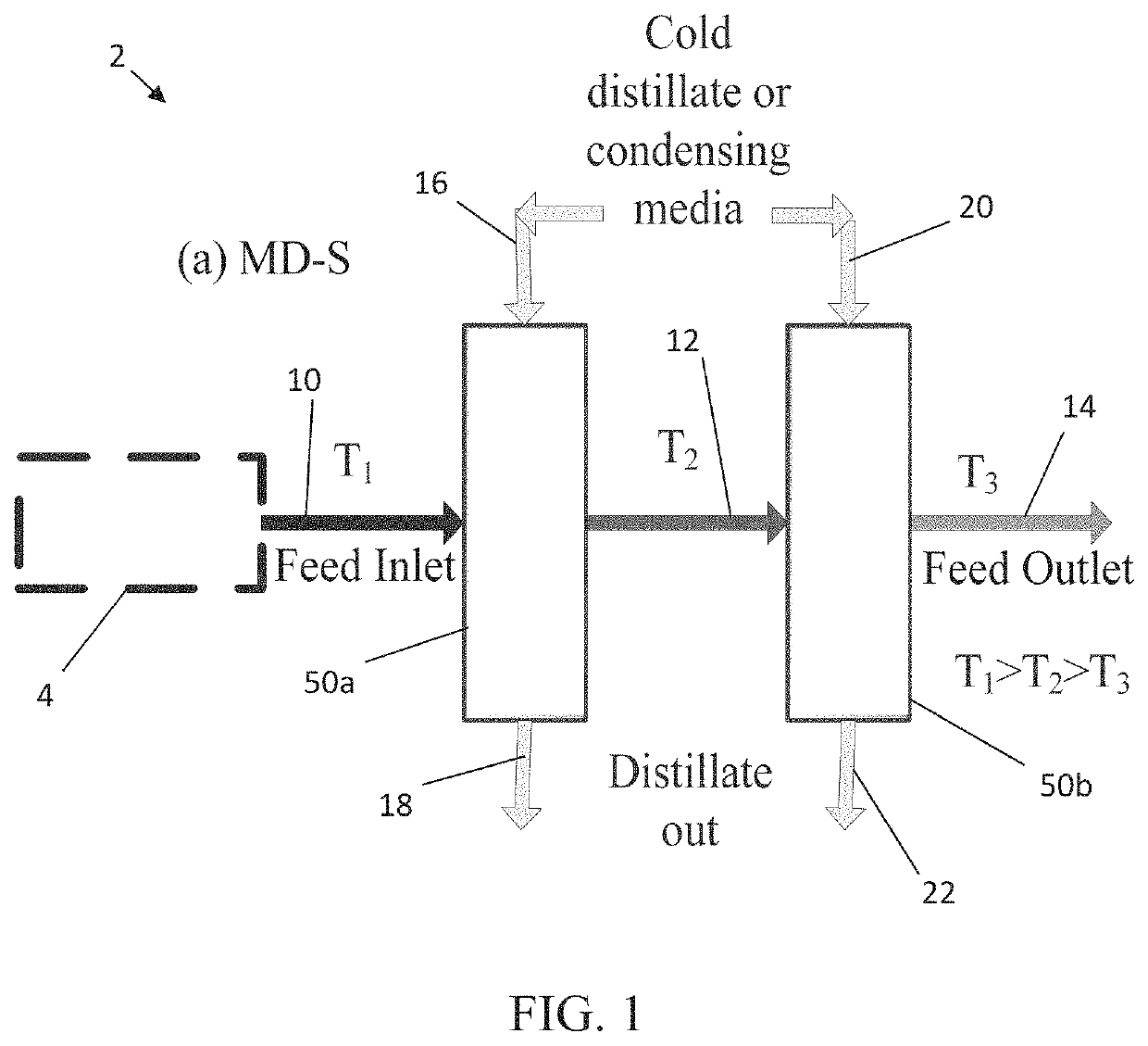
Embodiments disclosed herein include novel MD systems which may be used for desalination, and methods providing high water recovery and yield. MD is typically carried out at 60-90° C., which is significantly lower than conventional distillation processes. As a result, processes employing MD can potentially generate high quality drinking water using only low grade heat sources such as waste heat from industrial processes and solar energy. However, currently available MD desalination processes are characterized by low water recovery compared to other conventional systems. The systems and methods disclosed herein maximize solute rejection and flux, providing high water recovery from the feed. Though the presently disclosed subject matter has particular utility in desalination processes, the systems and methods disclosed herein may be employed in other applications.
In accordance with yet further embodiments herein, devices and methods are disclosed to maintain temperature uniformly in the feed side of a membrane module to maintain a high temperature gradient throughout the module, and enhance membrane flux.

Problems solved by technology

However, currently available MD desalination processes are characterized by low water recovery compared to other conventional systems.

Method used


Image

  • Systems and methods for maximizing recovery in membrane distillation
  • Systems and methods for maximizing recovery in membrane distillation
  • Systems and methods for maximizing recovery in membrane distillation

Examples


example 1

Now referring to FIGS. 9A-9C, the overall water recovery from a typical feed flow rate of 5 L / min was simulated. In FIG. 9A five small membrane modules M-1 through M-5 were arranged in series. Hollow fiber membrane modules were used for the experiments. However, the simulation is also useful for the modules of other configurations, such as flat sheet or spiral wound modules. In FIG. 9B a single large membrane module was deployed having a surface area equal to the cumulative surface area of the five smaller modules of the system of FIG. 9B. In FIG. 9C, four membrane modules M-1 through M-4 were arranged in parallel, the cumulative membrane surface area being comparable to that of the systems of FIGS. 9A and 9B. The flux was considered as 25 kg / m2·hr, and the feed inlet temperature was 80° C. at 10000 ppm concentration. Performance data of the membranes in each system are tabulated in Table 4. The data in Table 4 make clear that for a particular flow rate the water recovery is highest...


PUM

PropertyMeasurementUnit
areaaaaaaaaaaa
areaaaaaaaaaaa
temperatureaaaaaaaaaa

Abstract

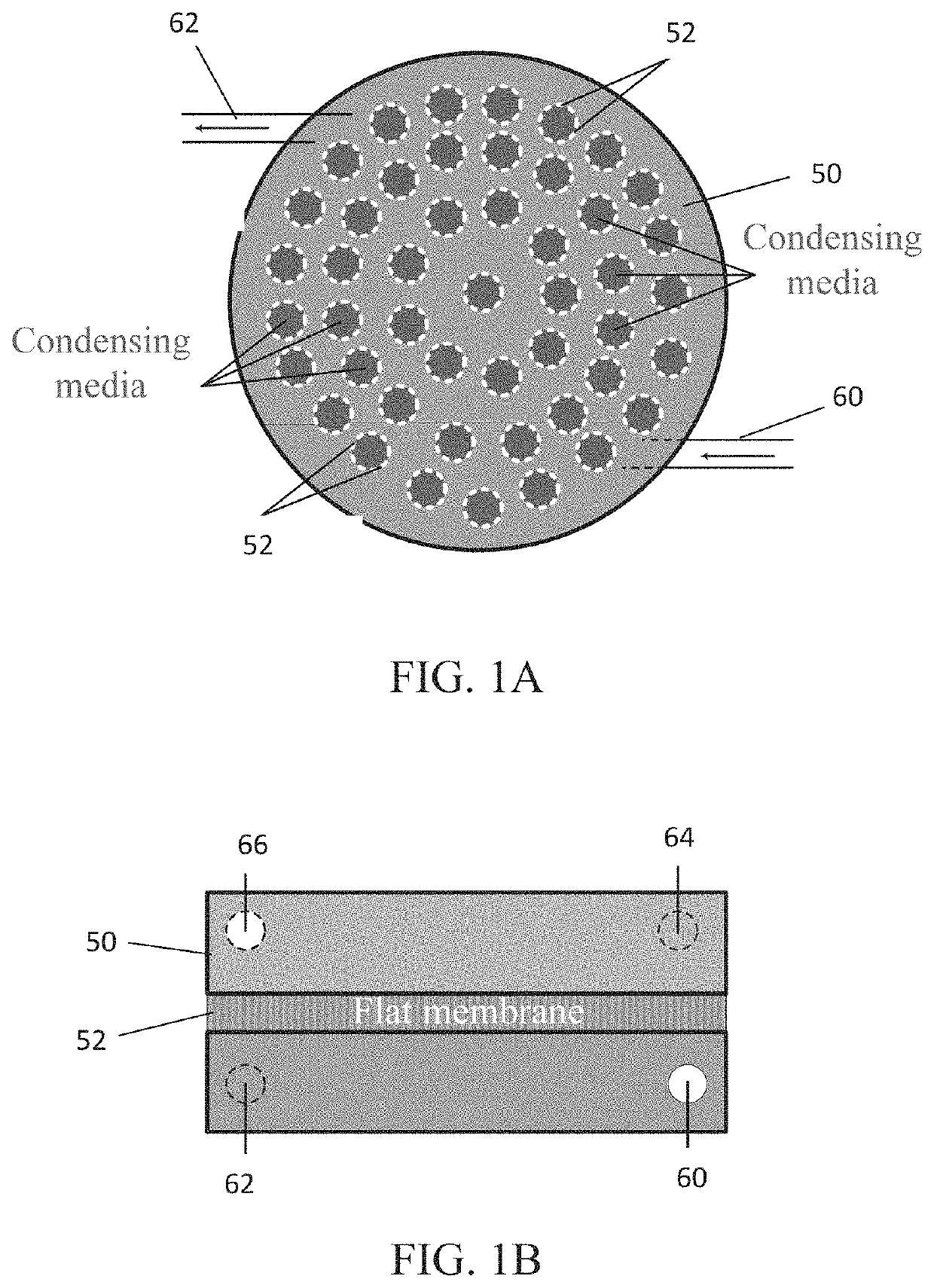
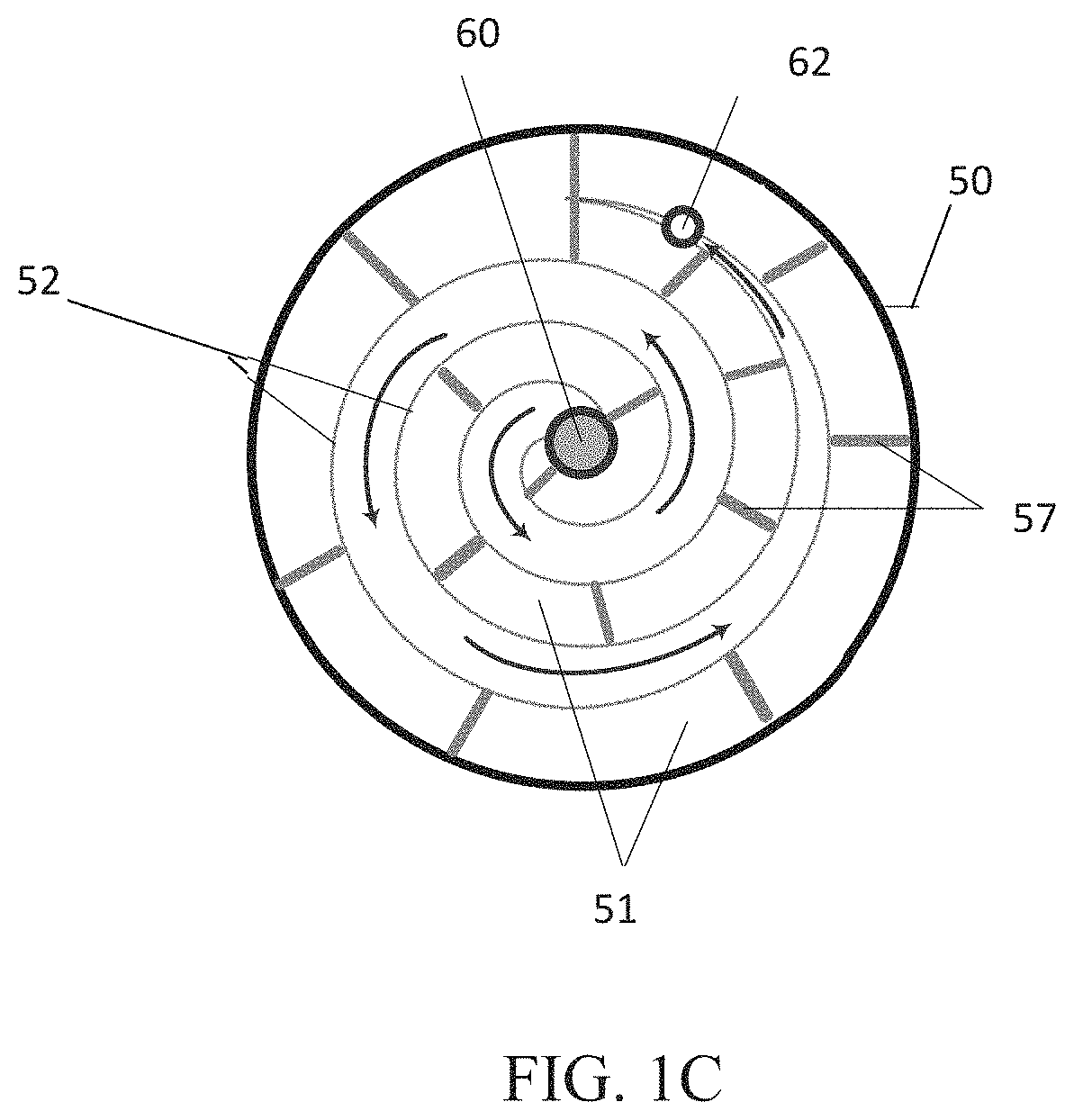
Membrane distillation (MD) systems include at least two MD modules arranged in series, each of at least two MD modules including a condensing media inlet operable to receive a condensing media and a condensing media outlet, a feed inlet operable to receive a feed media and a feed outlet, and a first heating element positioned and operable to heat a feed prior to or upon introduction of the feed to a first of the at least two MD modules, wherein a stream exiting the feed outlet of the first of the at least two MD modules is introduced to the second of the at least two MD modules. Other MD systems include at least two MD modules arranged in parallel.

Description

FIELD OF THE INVENTIONThis invention relates to membrane distillation and in particular to desalination systems and methods employing membrane distillation.BACKGROUND OF THE INVENTIONAs the shortage of clean water looms in the horizon, there is much interest in developing novel, cost effective desalination technology. Current methodologies include thermal, chemical and reverse osmosis. Membrane distillation (MD) has emerged as an alternative to address some of the issues related to the current technologies. MD is a membrane-based evaporation process in which the driving force is the temperature-induced vapor pressure difference caused by employing a hot feed and a cold permeate.SUMMARY OF THE INVENTIONEmbodiments disclosed herein include novel MD systems which may be used for desalination, and methods providing high water recovery and yield. MD is typically carried out at 60-90° C., which is significantly lower than conventional distillation processes. As a result, processes employi...

Claims


Application Information

Patent Timeline
Patent Type & Authority Patents(United States)
IPC IPC(8): B01D61/36B01D61/58C02F1/44B01D63/10C02F103/08
CPCB01D63/10B01D61/364C02F1/447B01D61/58B01D2317/04B01D2311/103B01D2317/022C02F2103/08B01D2317/02
Inventor MITRA, SOMENATHROY, SAGAR
Owner ROY SAGAR
Learn More