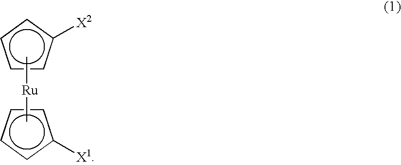
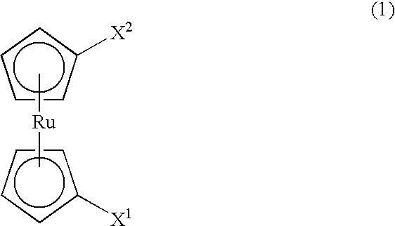
Ruthenium compound and process for producing a metal ruthenium film
a technology of metal ruthenium and compound, which is applied in the preparation of carboxylic compounds, ruthenium organic compounds, organic chemistry, etc., can solve the problems of inferior surface morphology of metal film formed by chemical vapor deposition, difficulty in ensuring the capacity of each memory cell with the prior art method, and preventing an increase in the capacity of the capacitor
- Summary
- Abstract
- Description
- Claims
- Application Information
AI Technical Summary
Benefits of technology
Problems solved by technology
Method used
Image

Examples
synthetic example 1
[0041]2.1 g of ruthenium carbonyl (Ru3(CO)12) was weighed and fed to a 200 ml flask whose inside had been substituted by nitrogen and left under reduced pressure at 50° C. for 30 minutes. After the temperature was returned to room temperature, the inside of the flank was substituted by dry nitrogen. 100 ml of well dried toluene and 60 ml of 1,5-cyclooctadiene purified by distillation were added in a nitrogen atmosphere. The obtained solution was heated at 100° C. and stirred for 9 hours. After the end of agitation, the solvent and unreacted cyclooctadiene were distilled off, and the residual viscous solution was let pass through a silica gel column using a hexane developing solvent in a nitrogen atmosphere to collect a dark brown fraction. After the solvent was dried, the mixture was sublimated at 80° C. under a reduced pressure of 133 Pa to obtain 0.8 g of cyclooctadienyl tricarbonyl ruthenium as a yellow needle crystal (yield rate of 31%).
synthetic example 2
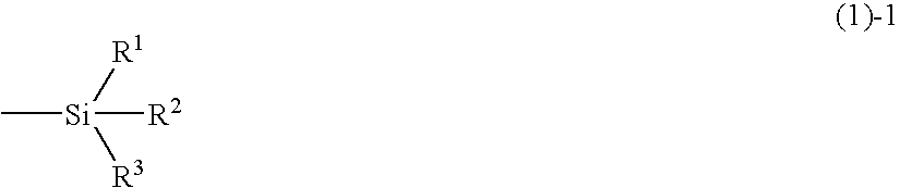
[0042]11 g of trimethylsilyl chloride was dissolved in 30 mol of well dried tetrahydrofuran in a 300 ml flask whose inside had been substituted by nitrogen, and the obtained solution was cooled to −78° C. 100 ml of a tetrahydrofuran solution (2.0 mol / l) of cyclopentadienyl sodium was added dropwise to the above solution in a stream of nitrogen over 1 hour. The solution was stirred at −78° C. for 1 hour and returned to room temperature over 6 hours. A salt precipitated in the mixture solution was removed by filtration in a nitrogen atmosphere, and the residual solution was distilled to obtain 8 g of trimethylsilyl cyclopentadiene.
[0043]0.5 g of metal sodium was mixed with a well dried tetrahydrofuran solution in a 300 ml flask whose inside had been substituted by nitrogen, and the resulting solution was cooled to −78° C. A solution of 2.5 g of the above synthesized trimethylsilyl cyclopentadiene dissolved in 30 ml of tetrahydrofuran was added dropwise to the above solution in a strea...
synthetic example 3
[0045]0.25 g of metal sodium was mixed with well dried tetrahydrofuran in a 100 ml flask whose inside had been substituted by nitrogen and cooled to −78° C. A solution of 1.3 g of trimethylsilyl cyclopentadiene dissolved in 30 ml of tetrahydrofuran was added dropwise to the above solution in a stream of nitrogen over 1 hour and heated to room temperature under agitation over 3 hours to obtain a tetrahydrofuran solution of trimethylsilyl cyclopentadienyl sodium.
[0046]Separately, 18 ml of a tetrahydrofuran solution (2.0 mol / l) of cyclopentadienyl sodium was prepared.
[0047]Further separately, 5 g of dichloro(1,5-cyclooctadienyl)ruthenium was dissolved in 200 ml of well dried tetrahydrofuran in a 500 ml flask whose inside had been substituted by nitrogen. This solution was cooled to −78° C., and the above tetrahydrofuran solution of trimethylsilyl cyclopentadienyl sodium and the above tetrahydrofuran solution of cyclopentadienyl sodium were added dropwise to the solution at the same tim...
PUM
| Property | Measurement | Unit |
|---|---|---|
| temperature | aaaaa | aaaaa |
| temperature | aaaaa | aaaaa |
| temperature | aaaaa | aaaaa |
Abstract
Description
Claims
Application Information
 - R&D
- Intellectual Property
- Life Sciences
- Materials
- Tech Scout
- Unparalleled Data Quality
- Higher Quality Content
- 60% Fewer Hallucinations
Browse by: Latest US Patents, China's latest patents, Technical Efficacy Thesaurus, Application Domain, Technology Topic, Popular Technical Reports.
© 2025 PatSnap. All rights reserved.Legal|Privacy policy|Modern Slavery Act Transparency Statement|Sitemap|About US| Contact US: help@patsnap.com