
Method for manufacturing ammonia synthesis catalyst, and method for manufacturing ammonia

a technology of ammonia synthesis and ammonia synthesis catalyst, which is applied in the direction of physical/chemical process catalysts, bulk chemical production, metal/metal-oxide/metal-hydroxide catalysts, etc., can solve the problems of increasing the load of manufacturing facilities and manufacturing costs, destroying micro-pores, and complicated reaction operations, etc., to achieve easy production, small reaction activity decrease, and high performance

Active Publication Date: 2022-02-01
TOKYO INST OF TECH +1
View PDF12 Cites 8 Cited by
  • Summary
  • Abstract
  • Description
  • Claims
  • Application Information

AI Technical Summary

Benefits of technology

The present inventors found that using a mayenite-type compound as a catalytic support without electron injection can result in a more efficient and stable catalyst for ammonia synthesis. This method is simpler and suitable for industrial production, providing a higher performance catalyst than traditional methods with a long lifetime and increased production efficiency.

Problems solved by technology

Therefore, the reaction operation becomes complicated.
There is concern that load of manufacturing facilities and manufacturing cost will increase.
Therefore, even a mayenite-type compound having micro-pores and having a large specific surface area is used, the micro-pores are destroyed when it is exposed to a high temperature condition.
As a result, there is a problem that further improvement in performance cannot be achieved because the specific surface area of the C12A7 electride is lowered during production of the catalyst.
In the production of the supported metal catalyst using the C12A7 electride as a catalytic support, there are problems in terms of manufacturing methods and manufacturing facilities, in a case of trying to improve the performance of the catalyst, and especially in a case of considering manufacturing on an industrial scale.

Method used


Image

  • Method for manufacturing ammonia synthesis catalyst, and method for manufacturing ammonia
  • Method for manufacturing ammonia synthesis catalyst, and method for manufacturing ammonia
  • Method for manufacturing ammonia synthesis catalyst, and method for manufacturing ammonia

Examples


example 1

[0215]Ca(OH)2 and Al(OH)3 were weighed and mixed to obtain a mixed powder so that the molar ratio of Ca atom to Al atom is Ca:Al=12:14. Distilled water was added to the mixed powder so that the amount of the mixed powder was 10 mass %. And a mixed solution having a total mass of 160 g was obtained. Thereafter, this mixed solution was stirred and mixed in a planetary ball mill at room temperature for 4 hours. The obtained mixed solution was placed in a pressure-resistant closed vessel while stirring, and was heated (hydrothermal treatment) at 150° C. for 6 hours.

[0216]About 20 g of a precursor powder of mayenite-type compound: Ca3Al2(OH)12 was obtained by filtering off, drying and pulverizing the precipitate obtained in the hydrothermal treatment. A powder of mayenite-type compound (hereinafter referred to as HT-C12A7) was obtained by heating and dehydrating the precursor powder in the air at 600° C. for 5 hours. The obtained mayenite-type compound is a compound having a large specif...

example 2

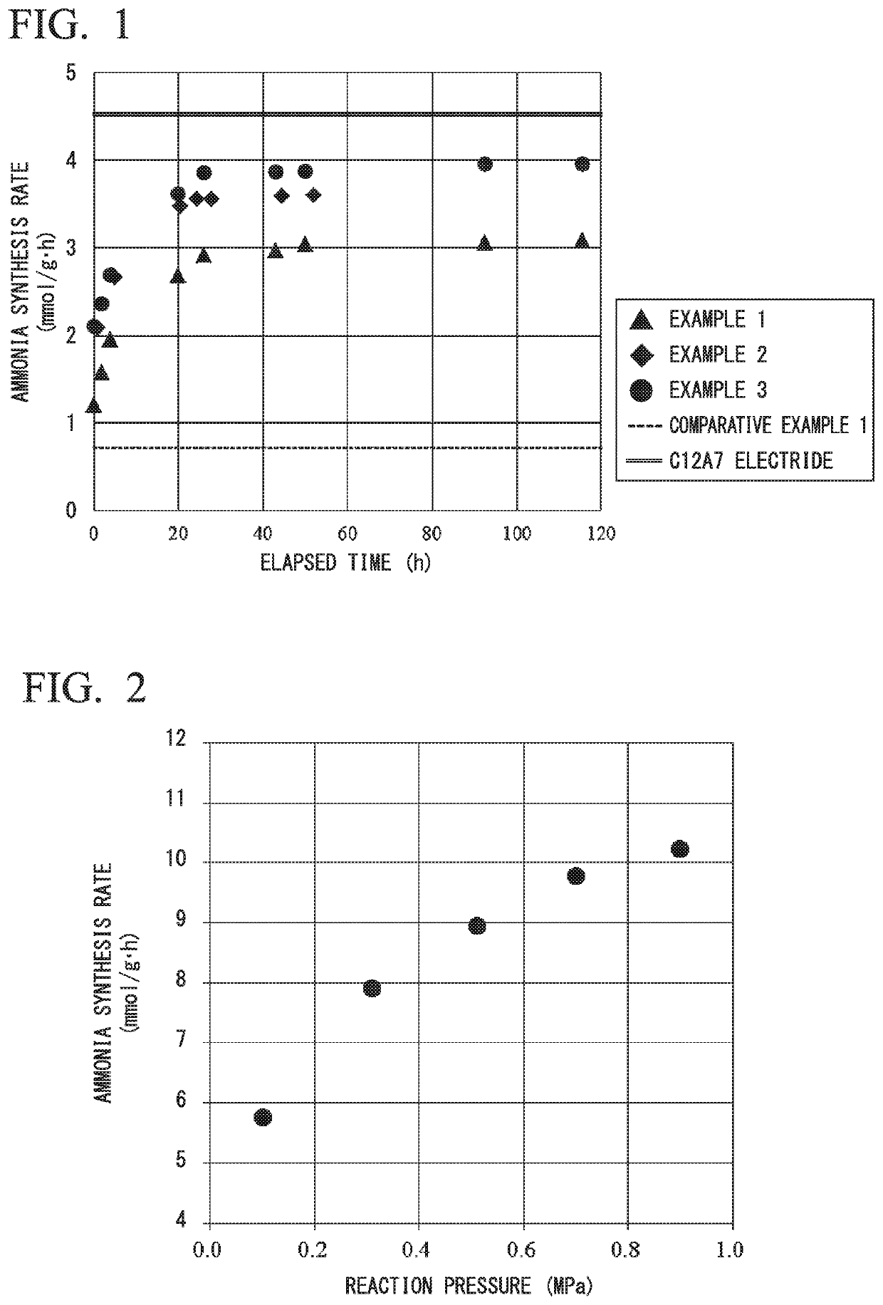
[0231]5 mass % Ru / HT-C12A7 was prepared in the same manner as in Example 1 except that the amount of Ru supported was 5 mass % was used. The obtained material was used as an ammonia synthesis catalyst reaction under the same conditions as in Example 1. Ammonia was synthesized under the same conditions as in Example 1. The results are shown in Table 1 and FIG. 1.

[0232]As shown in FIG. 1, a catalyst activity was greatly improved with the reaction time.

[0233]Also, as shown in Table 1, an initial synthesis rate of ammonia at 400° C. was 2.1 mmol / g·h, and the ammonia formation rate after about 24 hours reaction was 3.6 mmol / g·h.

[0234]The average particle diameter of Ru determined by the chemical adsorption method described above was 8.9 nm before the reaction and was 12.6 nm after the reaction. By the reduction process, the average particle diameter of Ru grew larger.

[0235]After that, although the reaction time was prolonged, no decrease in catalytic activity was observed.

example 3

[0236]10 mass % Ru / HT-C12A7 was prepared in the same manner as in Example 1 except that the amount of Ru supported was 10 mass % was used. The obtained material was used as an ammonia synthesis catalyst reaction under the same conditions as in Example 1. Ammonia was synthesized under the same conditions as in Example 1. The results are shown in Table 1 and FIG. 1.

[0237]As shown in FIG. 1, a catalyst activity was greatly improved with the reaction time.

[0238]Also, as shown in Table 1, an initial synthesis rate of ammonia at 400° C. was 2.1 mmol / g·h, and the ammonia formation rate after about 24 hours reaction was 3.9 mmol / g·h.

[0239]The average particle diameter of Ru determined by the chemical adsorption method described above was 10.7 nm before the reaction and was 14.0 nm after the reaction. By the reduction process, the average particle diameter of Ru grew larger.

[0240]After that, although the reaction time was prolonged, no decrease in catalytic activity was observed.


PUM

PropertyMeasurementUnit
specific surface areaaaaaaaaaaa

Abstract

Provided is a method for manufacturing a catalyst with which it is possible to obtain a supported metal ammonia synthesis catalyst, in which there are restrictions in terms of producing method and producing facility, and particularly large restrictions for industrial-scale producing, in a more simple manner and so that the obtained catalyst has a high activity. This method for manufacturing an ammonia synthesis catalyst includes: a first step for preparing 12CaO.7Al2O3 having a specific surface area of 5 m2 / g or above; a second step for supporting a ruthenium compound on the 12CaO.7Al2O3; and a third step for performing a reduction process on the 12CaO.7Al2O3 supporting the ruthenium compound, obtained in the second step. This invention is characterized in that the reduction process is performed until the average particle diameter of the ruthenium after the reduction process has increased by at least 15% in relation to the average particle diameter of the ruthenium before the reduction process.

Description

TECHNICAL FIELD[0001]The present invention relates to a method for manufacturing an ammonia synthesis catalyst and a method for manufacturing ammonia.[0002]Priority is claimed based on Japanese Patent Application No. 2016-155951 filed in Japan on Aug. 8, 2016, the contents of which are hereby incorporated by reference.BACKGROUND ART[0003]Nitrogen fertilizers, such as ammonium sulfate and urea, widely used in agricultural production, are produced using ammonia as a main raw material. Therefore, ammonia has been studied as a very important chemical raw material and its production method has been studied.[0004]The most widely used ammonia production technology is the Harbor-Bosch method. The Haber-Bosch method is a method for manufacturing ammonia, and the method includes contacting nitrogen and hydrogen as a raw material with a catalyst containing iron as a main component at high temperature and high pressure.[0005]As a synthesis method other than the Harbor-Bosch method, a synthesis ...

Claims


Application Information

Patent Timeline
Patent Type & Authority Patents(United States)
IPC IPC(8): B01J23/58B01J37/18C01C1/04B01J35/10B01J21/04B01J23/46B01J37/02B01J37/08
CPCB01J23/58B01J21/04B01J23/462B01J35/10B01J35/1009B01J37/0201B01J37/08B01J37/18C01C1/04C01C1/0411Y02P20/52B01J23/02B01J35/612B01J35/60
Inventor HOSONO, HIDEOKITANO, MASAAKIYOKOYAMA, TOSHIHARULI, JIANGKAWAMURA, SHIGEKIKISHIDA, KAZUHISA
Owner TOKYO INST OF TECH
Learn More