
Method and device for recording a three-dimensional distance-measuring image

a three-dimensional distance and image technology, applied in distance measurement, surveying and navigation, instruments, etc., can solve the problem of limited integration time, which is limited to about 30 ns, and achieves high signal level, easy evaluation, and relatively fast evaluation

Inactive Publication Date: 2007-05-01
ROCKWELL AUTOMATION
View PDF8 Cites 26 Cited by
  • Summary
  • Abstract
  • Description
  • Claims
  • Application Information

AI Technical Summary

Benefits of technology

[0008]The invention provides a method and device for recording a three-dimensional distance-measuring image by measuring light propagation times, in which an increased distance measuring range is achieved, the sensor signal is independent of the shape of the light-induced pulses, and a lower light output for the transmission side is facilitated.
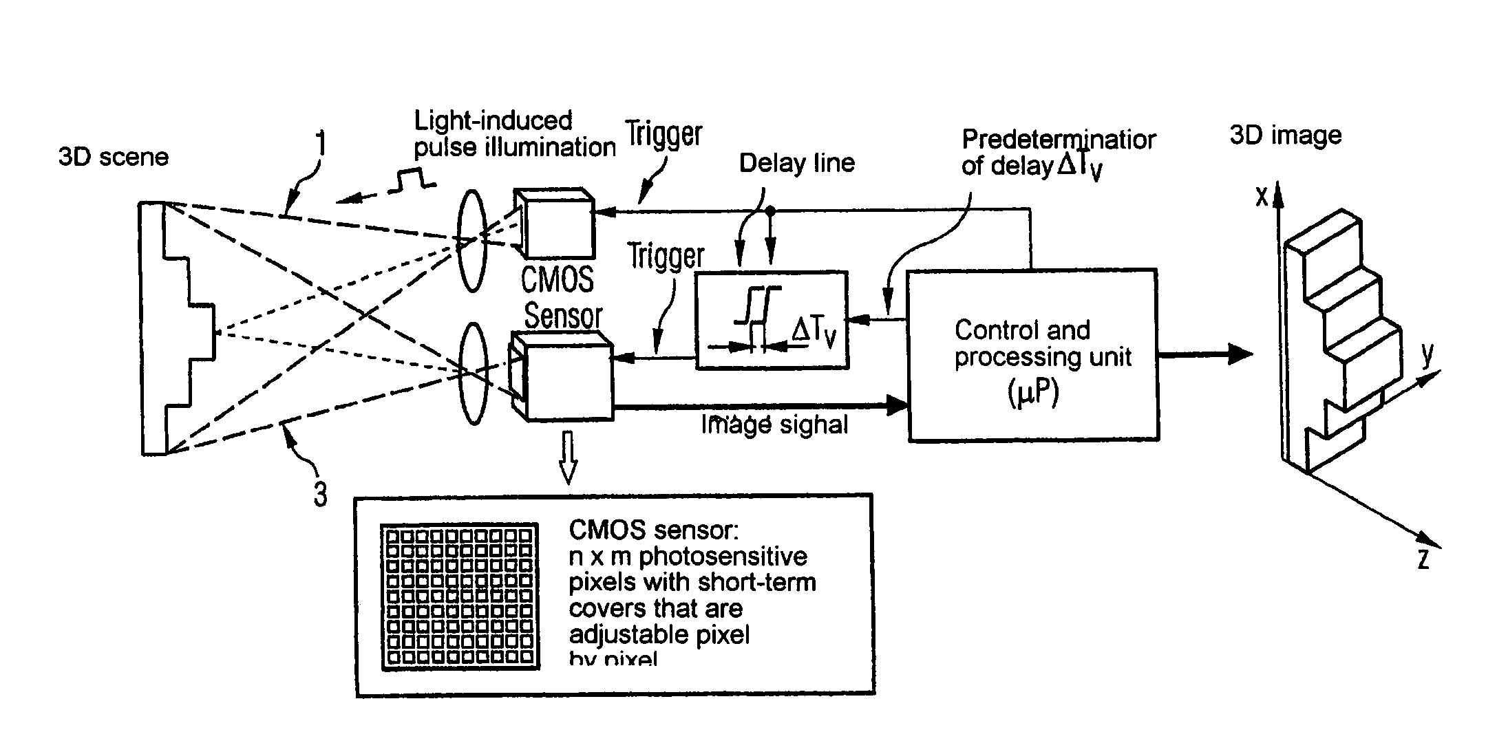
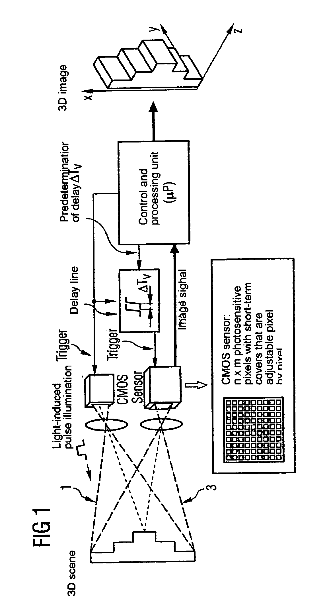
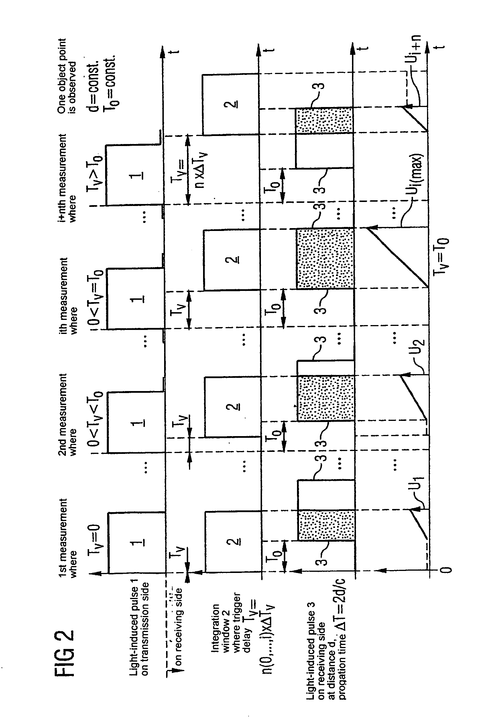
[0009]One embodiment of the invention uses a CMOS photosensor with a high number of pixels with short-term integration, in which the integration time can be adjusted pixel by pixel, and a light-induced pulse illumination for generating a 3D distance-measuring image. The light source used for this purpose is uniformly controllable, yet may also be of pointed or flat design. A new measurement principle is used for determining the distance values with the aim of facilitating reliable light propagation time measurements up to the noise level of the CMOS sensor. For this purpose, the emission of light-induced pulses on the transmission side by the trigger signals and the opening of the electronic shutter, which is synonymous with the opening of a time window, on the receiving side, is controlled on the CMOS sensor. This takes place on the receiving side with a gradually increasing time delay, for example via a delay line, in increments of—for example— 1 / 10 nanoseconds. In this way, the emitted laser pulse and the integration window are moved toward one another in time as the time delay increases, with at least one light-induced pulse being transmitted with each gradually increasing trigger delay. To reduce the laser pulse output, multiple light exposures are applied in all trigger delays if possible and a signal evaluation is carried out at the end. The integrated sensor signals measured in this way are stored in a processing unit.
[0012]Multiple illuminations are used to ensure that critical laser outputs do not exceed laser protection regulations. However, an essential benefit that can be attained in this way lies in the accumulation of several light-induced pulses arriving in succession at the integration cells. These are integrated in each light-induced pulse by the corresponding opening and closing of the integration cells, so that a sufficiently high signal level, which essentially depends on the noise range, is present at each integration cell. Thus it is possible, for the many integration cells whose local distribution corresponds to the pixel distribution of the image, to obtain a quantity of voltage signals, which, on the whole, can easily be evaluated. Since the time-consuming process of reading the multitude of integration cells takes place at the end of a multiple illumination, the evaluation is done relatively quickly.

Problems solved by technology

The integration time, however, is limited to about 30 ns for reasons relating to circuitry.

Method used


Image

  • Method and device for recording a three-dimensional distance-measuring image
  • Method and device for recording a three-dimensional distance-measuring image
  • Method and device for recording a three-dimensional distance-measuring image

Examples


Embodiment Construction

[0019]The total 3D scene to be measured is illuminated for an image record serially with short light-induced pulses with starting times in nanoseconds. The emission of the light-induced pulse is started via a trigger which is predetermined for each measurement process by a control and processing unit (FIG. 1). A part of the trigger signal is simultaneously guided via a programmable delay line and serves as the starting signal for opening the electronic shutter on the CMOS photosensor according to a predetermined time delay Tv with increments in the 1 / 10 nanosecond range, said shutter being closed again after a certain brief integration time (for example 30 ns). This is synonymous with the opening of a time window for receiving backscattered light-induced pulses 3. Incoming light-induced pulses may be integrated in an opened time window. The integration time, i.e. the duration that the window is open, is ideally selected as being equal to the duration of a light-induced pulse.

[0020]T...


PUM


Abstract

The invention relates to methods and devices for recording three-dimensional distance-measuring images of an object surface by measuring light propagation time using a short-term integrated photodetector. For starting a light-induced pulse on the transmission side, a trigger signal is produced that is at the same time used on the receiving side for opening at least one integration window for receiving back-scattered light-induced pulses with a predetermined time delay. A predetermined event such as a maximum or a zero crossing is detected which, by its interval relative to the integration windows, determines a trigger delay. The trigger delay is correlated with the light propagation time and allows calculation of the object point distance d.

Description

CLAIM FOR PRIORITY[0001]This application claims priority to International Application No. PCT / DE02 / 02843, which was published in the German language on Feb. 27, 2003, which claims the benefit of priority to Germany Application Nos. DE 101 38 531.5 and DE 101 53 742.5, which were filed in the German language on Aug. 6, 2001 and Oct. 31, 2001, respectively.TECHNICAL FIELD OF THE INVENTION[0002]The invention relates to a method and device for recording a three-dimensional distance-measuring image of an object, and in particular, by measuring light propagation times.BACKGROUND OF THE INVENTION[0003]The rapid, robust recording of three-dimensional images is becoming increasingly important in many fields, particularly in sensor technology. Because of the measurement basis required for the trigonometric calculation of a distance value, known triangulation methods are only suitable for distances of up to about 2 m and are of limited application. There is a great variety of applications for ...

Claims


Application Information

Patent Timeline
IPC IPC(8): G01C3/08G01B11/24G01S7/4865G01S7/487G01S17/08G01S17/18G01S17/894
CPCG01S7/487G01S17/89G01S7/4865G01S17/107G01S17/18G01S17/894G01S17/00
Inventor DOEMENS, GUNTERMENGEL, PETER
Owner ROCKWELL AUTOMATION
Learn More