
Device to produce round cross-section articles with complicated profiled surfaces

a technology of profiled surfaces and devices, which is applied in the direction of attachable milling devices, manufacturing tools, wood-turning machines, etc., can solve the problems of difficult cutting, need for complicated readjustment, and low productivity, and achieve the effect of low radial load and high level of smoothness of finished work surfaces

Inactive Publication Date: 2006-02-07
TECH COMMLIZATION
View PDF15 Cites 8 Cited by
  • Summary
  • Abstract
  • Description
  • Claims
  • Application Information

AI Technical Summary

Benefits of technology

[0012]It is yet a further object of the present invention to provide a lathe attachment device to produce a long-profiled article in a single transverse pass and with high accuracy.
[0013]It is yet a further object of the present invention to provide a device to produce a long-profiled article with high productivity.
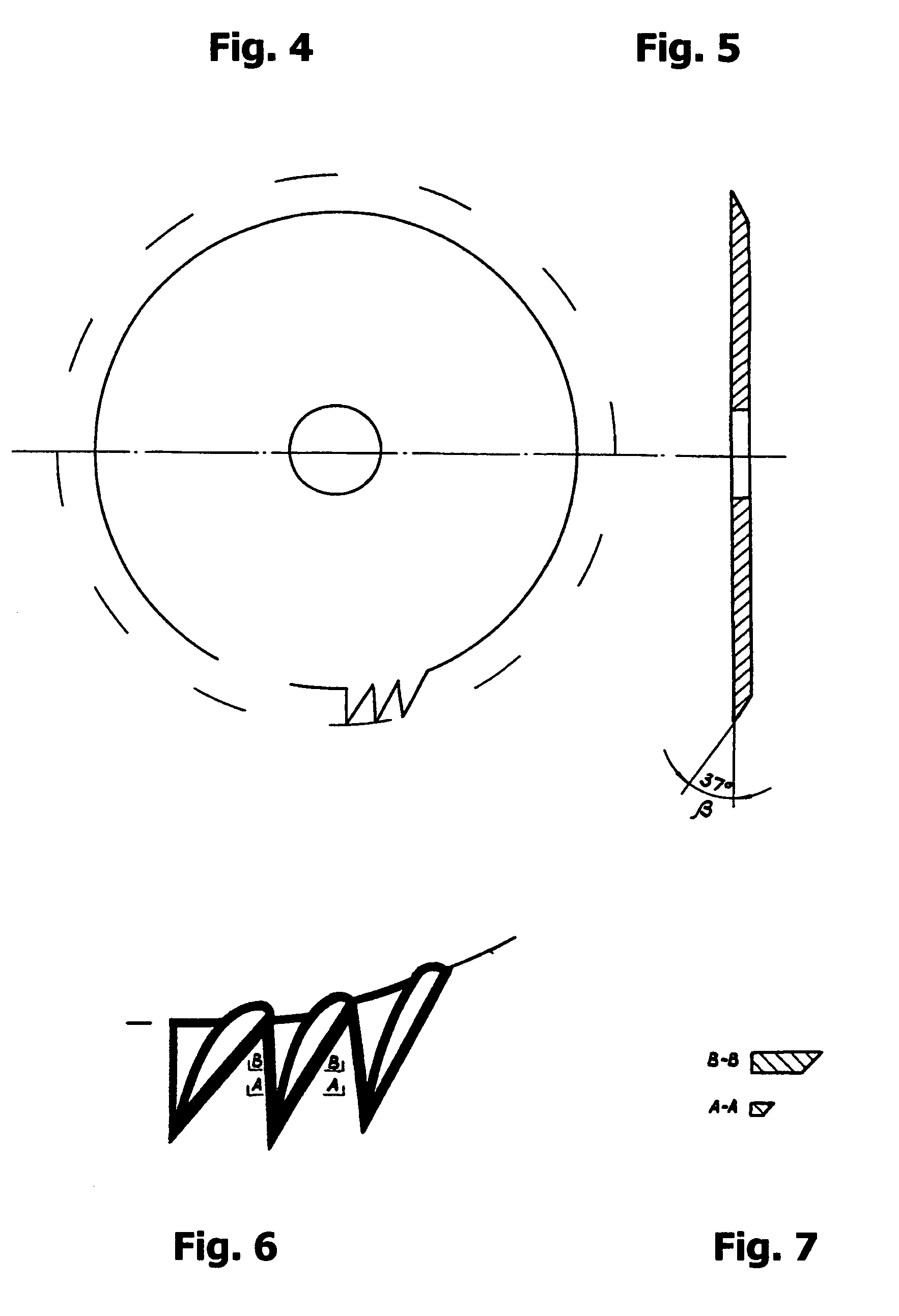
[0015]A cutter spindle is positioned in two orthogonal planes at acute angles to the main axis of a workpiece. The specially sharpened form-milling cutter is rotated in the opposite direction to the billet. Therefore, the cutter cuts the billet with the tip edges of its multi-edged acutely-shaped teeth, thus in turn only the few auxiliary edges facing the rough section of a billet (and only at the teeth tops) come in contact with the billet at each given point in time. This ensures minimal radial load on the billet and a high level of smoothness of the finished work surfaces, and also results in allowing the depth of the cut layer not to depend much on the teeth height of the milling cutter.

Problems solved by technology

The shortcomings of this processing device include low productivity, the necessity of using a guide roller on the template (which results in limitations when processing profiled articles with small curvature radii), difficulty with cutting when heavy radial loads are imposed on the billet, a need for complicated readjustment when producing a new configuration of articles having different shapes and hardness, and a relatively short durability period of single-toothed tools of varied nomenclature.
This lathe's disadvantage is the inability to process complicated curved surfaces.
The device requires a complex mechanism of turning the form-milling cutter due to the introduction of an additional copier while the main saddle is moved lengthwise along the major copier.
The disadvantage of this processing method is its low productivity due to the inability to increase the number of complicated profiled teeth within the form-milling cutter's limited diameter; the necessity to use a complex copying assembly with two guide rollers; and the need for a mechanism for constant readjusting of the slope angle of the form-milling cutter, while processing selected sections of a workpiece.
Additionally, the necessity of changing form-milling cutters to process parts with profiles having small curvature radii as well as the complicated adjustment procedure of the lathe and having to use expensive form-milling cutters reduce further the attractiveness of the device.
Finally, a wide form-milling cutter causes decreased productivity due to billet's heavy radial loads.

Method used


Image

  • Device to produce round cross-section articles with complicated profiled surfaces
  • Device to produce round cross-section articles with complicated profiled surfaces
  • Device to produce round cross-section articles with complicated profiled surfaces

Examples


Embodiment Construction

[0024]A detailed description of the present invention follows with reference to accompanying drawings in which like elements are indicated by like reference letters and numerals.

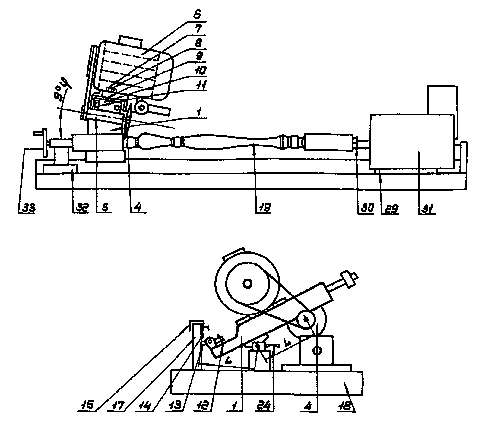
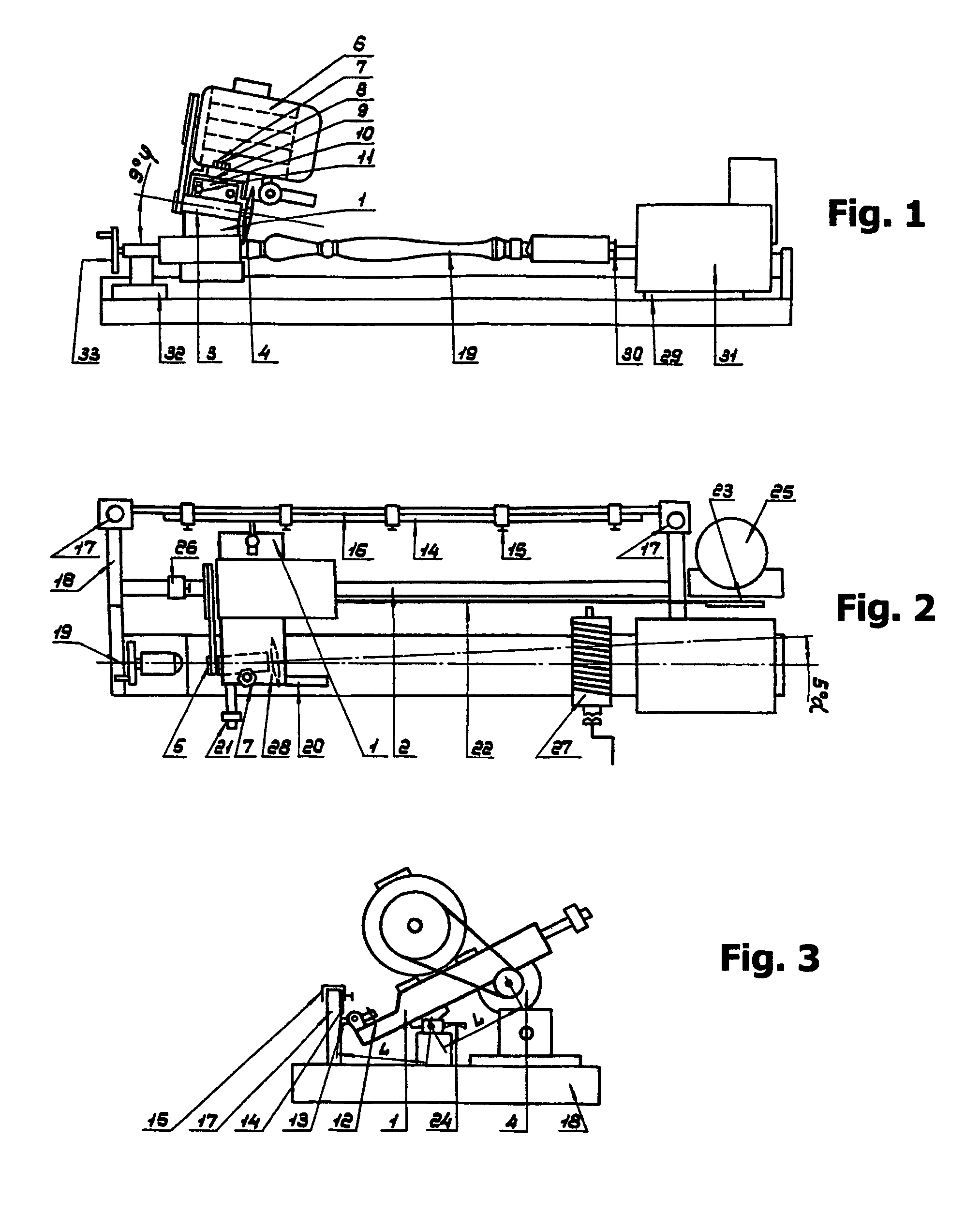
[0025]The attachment device is shown in detail on FIGS. 1, 2 and 3 and consists of the main saddle comprising a balancing unit 1 having two degrees of freedom to move relative to a cylinder guide 2. The balancing unit 1 carries a cutter spindle 3 with multi-teeth machining cutter 4 on slider bearings along the cylinder guide 2.

[0026]The cutter spindle 3 is rotated by means of drive belt 5 powered by an electric motor 6 fixed onto the balancing unit 1. It is possible to place the motor shaft and the cutter spindle coaxially if that is preferred. This way, the center of gravity of the balancing unit 1 is positioned above the cylinder guide 2. The cutter spindle 3 is fixed onto the balancing unit 1 and can move in two orthogonal planes (vertical and horizontal) at small acute angles α and φ to the axis of the c...


PUM

PropertyMeasurementUnit
anglesaaaaaaaaaa
anglesaaaaaaaaaa
anglesaaaaaaaaaa

Abstract

A lathe attachment device is disclosed for producing long articles with complicated profiles. The device contains a beveled multi-teeth cutter driven to rotate in a direction opposite the rotation of a billet to ensure a very short period of contact time between an individual cutting tooth and the article. The cutter is slightly tilted towards the billet in both horizontal and vertical plane. The teeth of the cutter are shaped to each have a pointed end facing the rough part of the billet. Provisions are made to draw the cutter along the billet. The device allows producing a smooth finished long article with complicated surface profile in a single pass with high productivity. Due to limited contact time, it offers extended life of the cutter. The device is used most advantageously to produce long wood articles.

Description

CROSS-REFERENCE DATA[0001]This application is a continuation-in-part of a PCT application No. PCT / RU02 / 00393 with the same title filed 20 Aug. 2002, which in turn claims priority from a patent application of the Russian Federation No. 2001123379 filed 21 Aug. 2001.BACKGROUND OF INVENTION[0002]The present invention relates generally to the field of lathes and mechanical processing of long, semi-rigid shafts (billets). More particularly, the device of the invention may be used advantageously as an attachment to a lathe to produce round cross-section articles with complicated profiled surfaces out of wood and other materials, including plastic, metal and composites. The instant invention should preferably be used to process wood workpieces.[0003]Lathes equipped with automatic copying attachments are generally known. Russian Patent No. 338367 describes for example a profile turning automatic lathe allowing to make articles of round cross-section having complicated profiled surfaces. A r...

Claims


Application Information

Patent Timeline
Patent Type & Authority Patents(United States)
IPC IPC(8): B23B3/26B23C3/04B23C7/02B23Q11/00B23Q35/00B27C7/00B27C7/06
CPCB23C3/04B23C7/02B23Q11/0021B23Q11/0032B23Q35/00B27C7/005B27C7/06Y10T82/14Y10T409/301624Y10T29/5109Y10T409/305656Y10T82/2529Y10T409/303808Y10T409/309688
Inventor KRUKOV, ALEXANDR IVANOVICH
Owner TECH COMMLIZATION
Learn More