Optical recording medium

a recording medium and optical technology, applied in the field of optical recording media, can solve the problem of somewhat losing storage reliability of the medium, and achieve the effect of satisfactory recording/reading characteristics and high storage reliability

Inactive Publication Date: 2005-07-26
TDK CORPARATION
View PDF23 Cites 5 Cited by
  • Summary
  • Abstract
  • Description
  • Claims
  • Application Information

AI Technical Summary

Benefits of technology

[0015]An object of the present invention is to provide an optical recording medium having a high storage reliability and satisfactory recording / reading characteristics.

Problems solved by technology

However, it was found that when the second dielectric layer 32 is formed of Al2O3 or SiO2, the medium somewhat loses storage reliability on account of a likelihood of separation between the second dielectric layer 32 and the recording layer 4 when the medium is stored under hot humid conditions.

Method used


Image

  • Optical recording medium
  • Optical recording medium

Examples


example

Example 1

[0063]Sample No. 1

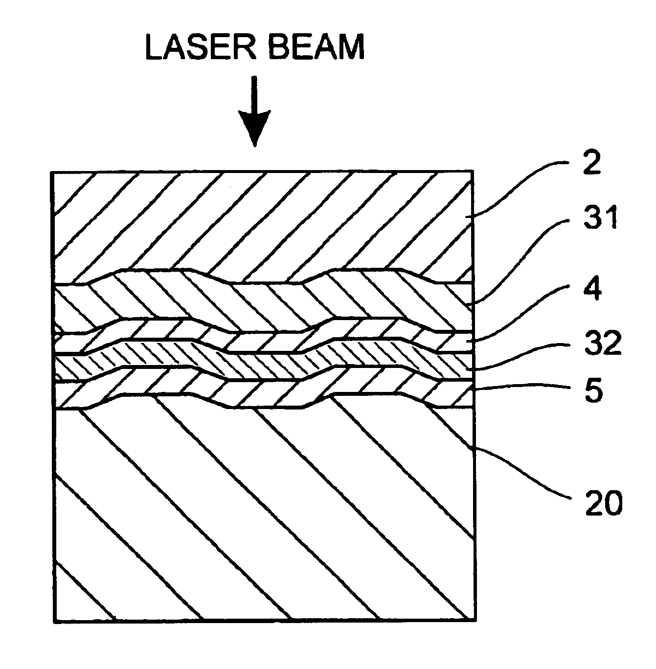
[0064]An optical recording disk sample of the structure shown in FIG. 1 was prepared by the following procedure.

[0065]The support substrate 20 used was a disk-shaped polycarbonate having a diameter of 120 mm and a thickness of 1.1 mm in which grooves were formed simultaneous with injection molding.

[0066]The reflective layer 5 was formed in an argon atmosphere by a sputtering process. The target used was Ag98Pd1Cu1. The reflective layer 5 was 100 nm thick.

[0067]The second dielectric layer 32 was formed in an argon atmosphere by a sputtering process using a composite target of CeO2—Al2O3. The composite target had the composition of CeO2:Al2O3=80:20 (molar ratio). The second dielectric layer 32 was 12.5 nm thick.

[0068]The recording layer 4 was formed in an argon atmosphere by a sputtering process using an alloy target. The recording layer 4 had the composition (atomic ratio):

(SbxTe1-x)1-yMy  I

wherein M=In and Ge in a ratio of 1:5, x=0.78, and y=0.06. The reco...

example 2

[0084]Optical recording disk samples were prepared by the same procedure as sample No. 1 except that the second dielectric layer 32 was formed of CeO2—Al2O3 or CeO2, the Al2O3 content in the second dielectric layer 32 was changed as shown in Table 1, and the thickness of the second dielectric layer 32 was changed as shown in Table 1. It is noted that the thickness of the second dielectric layer 32 in each sample was set such that the reflectance was identical in all the samples.

[0085]For these samples, the optimum recording power Pw which produced a minimum jitter was determined under the same conditions as in Example 1. Also, these samples were stored in a hot humid environment as in Example 1 and examined whether separation occurred between the recording layer 4 and the second dielectric layer 32 after the storage. The results are shown in Table 1.

[0086]

TABLE 1SampleAl2O3ThicknessPwNo.(mol %)(nm)(mW)Separation4—8.06.0no(comparison)5108.06.0no6208.55.8no7409.05.7no86010.05.6no98011...


PUM

PropertyMeasurementUnit
thicknessaaaaaaaaaa
thicknessaaaaaaaaaa
thicknessaaaaaaaaaa

Abstract

The optical recording medium of the invention comprises a recording layer and at least one mixed dielectric layer. The mixed dielectric layer contains cerium oxide and an additive compound. The additive compound is at least one compound selected from among aluminum oxide, chromium oxide, iron oxide, manganese oxide, niobium oxide, magnesium oxide, zinc oxide, titanium oxide, yttrium oxide, tantalum oxide, antimony oxide, zirconium oxide, bismuth oxide and magnesium fluoride. The optical recording medium has a high storage reliability and satisfactory recording / reading characteristics.

Description

CROSS-REFERENCES TO RELATED APPLICATIONS[0001]This application is a continuation of International PCT Application No. PCT / JP02 / 12223, filed on Nov. 22, 2002 which claims priority to Japanese patent application No. JP 2001-357160 in the Japanese Patent Office.TECHNICAL FIELD[0002]This invention relates to optical recording media such as phase change media and the like.BACKGROUND ART[0003]Great attention is now paid to optical recording media capable of high density recording and erasing the once recorded information for rewriting. Among such rewritable optical recording media, phase change recording media are designed such that recording is performed by irradiating a laser beam to a recording layer to change its crystalline state and reading is performed by detecting the change of reflectance of the recording layer associated with that state change. The phase change optical recording media are of greater interest because the drive unit may have a simple optical system as compared wit...

Claims


Application Information

Patent Timeline
Patent Type & Authority Patents(United States)
IPC IPC(8): G11B7/243G11B7/24G11B7/257G11B7/258G11B7/2578G11B7/2542G11B7/259
CPCG11B7/243G11B7/259G11B7/257G11B7/006G11B7/2542Y10T428/21G11B7/258G11B2007/25715G11B7/2578
Inventor INOUE, HIROYASUISHIZAKI, HIDEKITAKASAKI, HIROSHIHIRATA, HIDEKI
Owner TDK CORPARATION
Why Eureka
Try Eureka