Incubator having combined HEPA and VOC filter

Inactive Publication Date: 2005-04-12
THERMO FISHER SCI ASHEVILLE
View PDF103 Cites 39 Cited by
  • Summary
  • Abstract
  • Description
  • Claims
  • Application Information

AI Technical Summary

Benefits of technology

The controlled atmosphere incubator of the present invention solves the problems and eliminates the drawbacks described in the background of the invention. It does so by providing a controlled atmosphere incubator including a cabinet in thermal communication with a heater for maintaining a required temperature. The cabinet includes top, bottom, rear, and side walls defining an interior chamber of the incubator. Access to this interior chamber is provided by a door pivotally mounted to the front of the incubator. A blower is mounted within the chamber and includes both an inlet and an outlet for aiding in air circulation within the chamber. The chamber also includes an upper plenum partially formed by a plate mounted across the chamber and between the inlet and outlet of the blower. The circulation of air in the incubator proceeds through this upper plenum which then adjoins a side plenum that conveys the air to an opening in the base of the process chamber. A VOC filter is operatively connected to the inlet of the blower to filter VOCs from the atmosphere of the incubator. This need not be a physical connection, but one which facilitates the filtering function. This VOC filter surrounds a HEPA filter which removes particulate matter from the atmosphere of the chamber. The VOC and HEPA filters are integrated into the air flow system of the incubator chamber itself and are contained within the gaseous environment of the incubator chamber.
The VOC and HEPA filter elements are contained directly within the gaseous environment of the incubator chamber. One benefit of this improvement is that VOC contamination is eliminated from the gas mixture as it is quickly and completely circulated through the incubator. Since the combined filter is integrated as part of the standard blower system of the incubator, and since the air moves at 6-7 cfm through the filter, the entire mass of air in the processing chamber is filtered approximately once a minute in a chamber having a volume of 6.5 cfm. This filtering occurs much more rapidly than in incubators of the prior art while eliminating both VOCs and particulate materials. As a result, the purity of the gas mixture within the process chamber will be enhanced over other filter systems.
Additionally, the location of the VOC and HEPA filters in the interior of the incubator chamber tremendously simplifies any repair or replacement procedures over those necessary with incubators of the prior art. The filters are easily removed and replaced by a researcher or other user from within the chamber and do not require the removal of side panels or other hardware which might involve exposure to high voltage wiring and / or components.

Problems solved by technology

Problems which existed with such air circulation systems included the requirement for an additional heat source to maintain the temperature of the HEPA filter above the dew point of the air mixture.
However, particulate materials are not the only potential source of contamination in an incubator.
VOCs are not removed by a HEPA filter, and as such, could have a harmful effect on the samples within the incubator chamber.
Sources of VOC contamination in the laboratory include general air contamination, cleaning agents, and off-gassing laboratory equipment and plasticware.
Compounds and solutions used in culturing techniques may also contribute to contamination by unwanted VOCs.
While U.S. Pat. No. 6,013,119 is one example of a VOC filter being used in conjunction with an incubator, a number of drawbacks still exist with the apparatus and method disclosed in that patent.
However, an increase in the time it takes a VOC filter to decontaminate one cycle of air correlates to an increased amount of time that any VOC may remain viable in the incubator prior to passing through the filter.
These problems are compounded by, and some additional problems arise from, the location of the VOC filter in conjunction with currently existing incubators.
This increases the distance the air stream must travel and thus the time necessary for filtering one cycle of air.
Also, the location of the VOC filter may make it difficult to reach for repair, replacement, and / or cleaning.
This results in problems of increased expense and time to perform these maintenance functions.
All these problems may ultimately result in an increased degree of VOC contamination of the contents of the incubator.

Method used


Image

  • Incubator having combined HEPA and VOC filter
  • Incubator having combined HEPA and VOC filter
  • Incubator having combined HEPA and VOC filter

Examples


Embodiment Construction

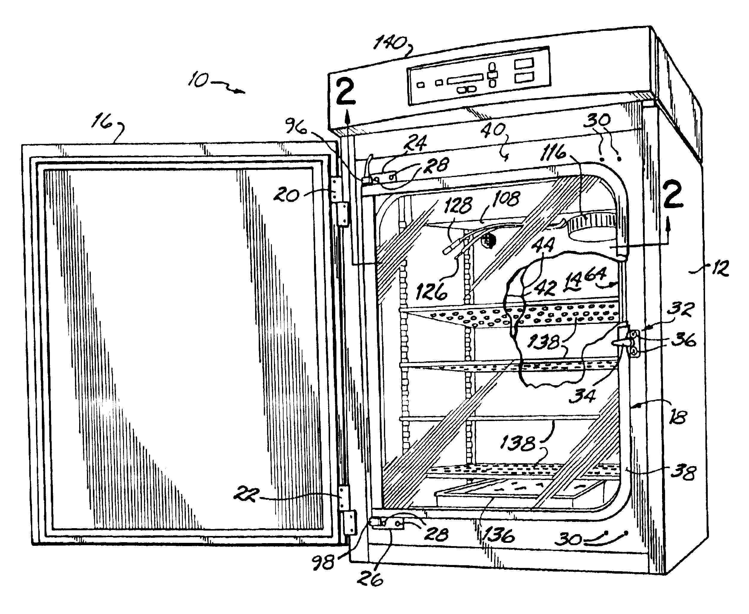
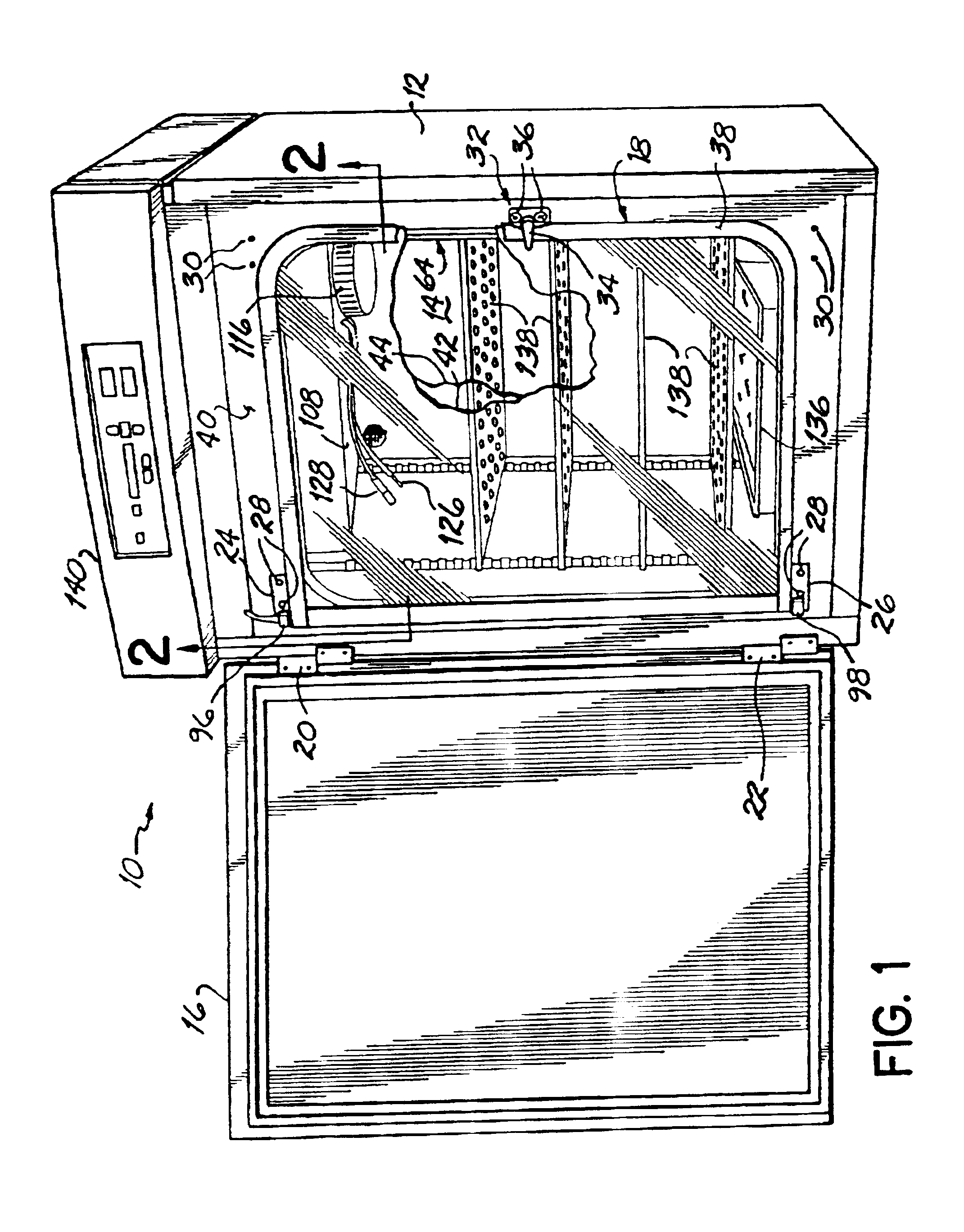
FIG. 1 illustrates an incubator 10 constructed in accordance with the present invention and generally including an insulated, and preferably water-jacketed, cabinet 12 with an interior controlled-atmosphere chamber 14. Chamber 14 is accessed through a pair of doors which include an outer insulated door 16 and an inner heated glass door 18. Insulated door 16 is attached to cabinet 12 by a pair of hinges 20, 22 which may be alternatively attached to the left or right side of cabinet 12 depending on which direction it is desired to swing insulated door 16. Likewise, inner glass door 18 includes hinges 24, 26 secured by fasteners 28 to front panel 40 of cabinet 12. In general these fasteners 28 and receiving elements 30 allow fastening of door 18 to front panel 40 in either a left or right swinging manner. Fastener receiving elements 30 are installed permanently on both the left and the right side of front panel 40 and are sealed into the water jacket portion of cabinet 12. Door 18 furt...


PUM

PropertyMeasurementUnit
Flow rateaaaaaaaaaa

Abstract

A controlled atmosphere incubator having an interior chamber adapted to be heated and humidified. An easily accessed blower is located within the gaseous environment of the incubator chamber and includes a HEPA filter and VOC filter readily replaceable by the user from within the chamber.

Description

FIELD OF THE INVENTIONThe present invention is generally related to controlled atmosphere incubators and, more specifically, to an improved incubator used to culture biological specimens.BACKGROUND OF THE INVENTIONIncubators are used in laboratories to maintain as viable bacteria, cells, tissues, and other biological specimens. Incubators accomplish this by providing a controlled environment. There are many parameters of the incubator environment which require control. These include temperature, humidity, and the concentration of gases such as oxygen and carbon dioxide, among others. An air circulation system is a vital ingredient in creating the correct environmental conditions for the growth of cell cultures in a laboratory incubator. Air circulation is needed to maintain temperature uniformity within the chamber and also to effectively distribute and mix the various gases, such as CO2 and N2, used to control the pH and O2 levels within the chamber. The air flow keeps the lighter ...

Claims


Application Information

Patent Timeline
IPC IPC(8): B01D46/10B01D46/12B01D53/02B01D46/00B01D46/24
CPCB01D46/0024B01D46/0036B01D46/2411B01D53/02C12M41/14B01L1/025B01L1/50C12M37/02B01D2267/40B01L2300/10B01L2300/0681B01D46/64
Inventor LOHR, DAVIDWAGER, RAQUEL
Owner THERMO FISHER SCI ASHEVILLE
Why Eureka
Try Eureka