Method for rapid mold heating and cooling
a technology of thermoplastic materials and molds, applied in auxillary shaping apparatuses, manufacturing tools, coatings, etc., can solve the problems of residual stresses, difficult molding thin sections, and difficult molding processes of conventional molding processes, so as to shorten the molding cycle time, rapid heating and cooling, and improve the effect of part quality
- Summary
- Abstract
- Description
- Claims
- Application Information
AI Technical Summary
Benefits of technology
Problems solved by technology
Method used
Image
Examples
example 1
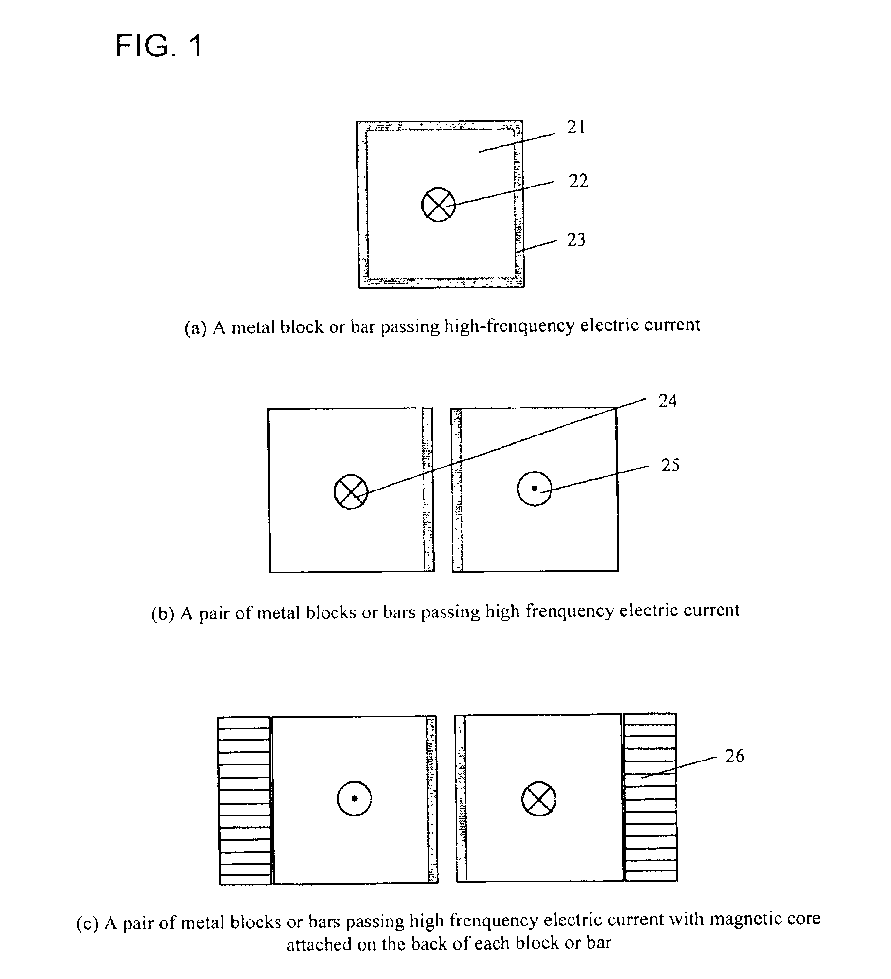
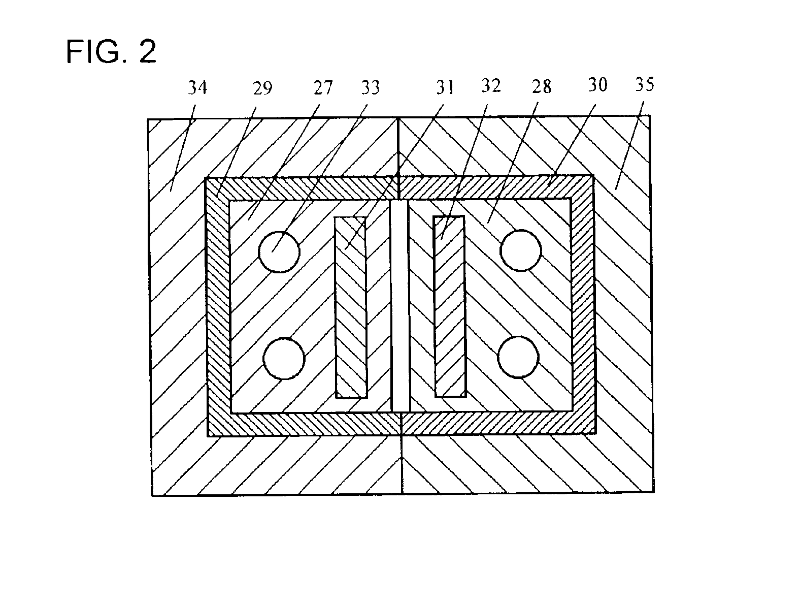
Two mold inserts developed for proximity heating were constructed first. Conformable cooling channels are embedded in the two inserts. The two inserts were placed on a flat insulation top, facing each other with a gap about 1 mm in-between. High frequency (˜650 KHz) current is applied to the electric loop formed by the two mold inserts facing each other. Due to the proximity effect, most current flows at the inner surfaces of the two inserts, thus rapidly heating the surface of the formed gap. The power applied is around 2.5 KW. Once designated temperature is reached, the power is turned off and the insert surface starts to cool down. A typical surface temperature response of the mold insert is shown in FIG. 5. The insert surface can be rapidly heated from room temperature to 250° C. in two seconds and then rapidly cooled to 50° C. in less than 10 seconds.
example 2
Heat transfer simulation results are presented in this example to illustrate the advantage of using the rapid heating and cooling mold insert as described in Example 1 to reduce injection molding cycle time. The molding process using the rapid heating and cooling mold insert is termed Rapid Thermal Response (RTR) molding in the description. Polycarbonate samples with varied thickness, 0.5 mm, 1 mm, 2 mm and 4 mm are considered in the simulation. The experimental cavity surface temperature as shown in FIG. 5 is used as the temperature boundary for the part. For comparison, the case of conventional injection molding was also simulated. The processing parameters for both cases are listed in the following:
Processing ParametersConventional MoldingRTR MoldingMelt temperature, ° C.320320Mold temperature, ° C.11025Ejection Temperature, ° C.130130
The cycle time comparison between the two processes is shown in FIG. 6. For the two thin samples, the 0.5 mm thick one and the 1.0 mm thick one, th...
example 3
A set of mold inserts designed for proximity heating were made first. Closure of the two inserts forms a rectangle mold cavity, 72 mm long and 25 mm wide, with the thickness adjustable. Polycarbonate was chosen as molding material. The so constructed mold has a capability of raising surface temperature from 25° C. to above 200° C. within 5 seconds and cooling to a temperature blow the polycarbonate ejection temperature in less than 15 seconds, as shown in FIG. 7. No cooling channels were made in the two inserts. The cooling rate can be further increased by embedded cooling channels directly inside the two inserts as illustrated in FIG. 3 and FIG. 4 and shown in Example 1. The maximum power of the high-frequency power supply used in the experiment is less than 3 KW. The heating rate can be further increased by using a power supply with higher power output.
The injection molding experiments were carried out on a 30-ton BOY® injection molding machine. FIG. 8 shows the effect of heating ...
PUM
| Property | Measurement | Unit |
|---|---|---|
| Thickness | aaaaa | aaaaa |
| Thickness | aaaaa | aaaaa |
| Frequency | aaaaa | aaaaa |
Abstract
Description
Claims
Application Information
 - R&D
- Intellectual Property
- Life Sciences
- Materials
- Tech Scout
- Unparalleled Data Quality
- Higher Quality Content
- 60% Fewer Hallucinations
Browse by: Latest US Patents, China's latest patents, Technical Efficacy Thesaurus, Application Domain, Technology Topic, Popular Technical Reports.
© 2025 PatSnap. All rights reserved.Legal|Privacy policy|Modern Slavery Act Transparency Statement|Sitemap|About US| Contact US: help@patsnap.com


