Chemical reactor system and process

Inactive Publication Date: 2004-03-09
SABIC GLOBAL TECH BV
View PDF141 Cites 25 Cited by
  • Summary
  • Abstract
  • Description
  • Claims
  • Application Information

AI Technical Summary

Benefits of technology

The reactor includes a supported catalyst bed through which the reactants flow to catalytically produce the final bisphenol. The flow preferably used is a supported downflow mode in which reactant materials flow co-currently from a higher elevation to a lower elevation through the bed to facilitate the chemical reaction to produce the bisphenol product. Although the method is applicable to the production of any isomer of bisphenol, the preferred isomer is p,p'-bisphenol A produced by the reaction of phenol with acetone (dimethyl ketone) in the presence of an 
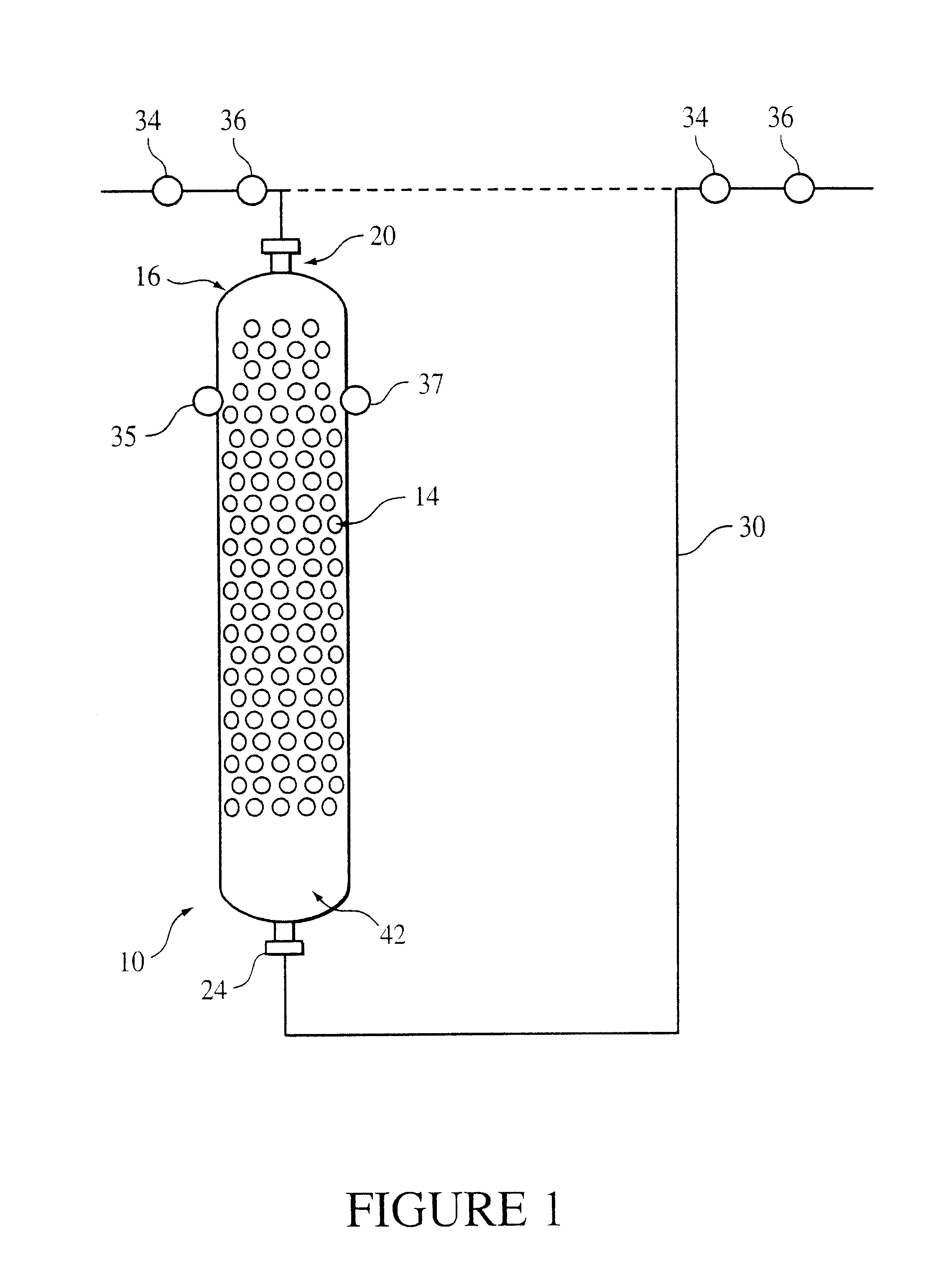
ion exchange resin catalyst which may optionally be modified by selected promoters such as, for example, mercaptan compounds, if desired. The reactor is shown in FIG. 1 at 10 and includes a bed 14 containing an ion exchange resin catalyst and randomly dispersed packing. The bed receives co-current downflow streams of the reactants. The ion exchange resin catalyst is distributed around the packing so that the catalyst is supported within the bed to minimize channeling and compressive forces, as well as to optimize the hydraulic performance of the reactor. Any type of reactor vessel used to react reactants in the presence of fixed catalyst is generally amenable to practicing this invention. However, cylindrical reactors are preferred for their simplicity.
The random arrangement of the packing in the shell provides support for the resin catalyst and minimizes compression. "Settling" of the catalyst is essential and desirable to insure complete filling of the void spaces within the catalyst bed. The packing also ensures that the cumulative compressive forces (which are the sum of the forces created by gravity and the viscous drag from the downflow of reactants) are interrupted to such a degree that high conversion, high selectivity, and long lifetime can be realized by the resin catalyst. The minimization of the compressive forces is enough that the "wall effects" of the packing elements are spread through the bed on a microscopic scale.
This type of inert random packing interrupts the packing structure of the spherical resin particles to provide a larger effective void fraction. The resin bed alone usually has a void fraction of about 0.36 and small increases in this is expected to result in dramatic decrease in pressure drop. Although decreased pressure drop caused by increased void fraction is less desirable than that caused by preventing compression, since the increased void fraction represents paths for "channeling" or "short circuiting", which reduces the contact time of the reactants and catalyst. Increasing the void fraction within the catalyst is less desirable than simply preventing the decrease of void fraction caused by bead deformation.
Preferably, the packing comprises metallic cascade rings, such as CASCADE MINI-RINGS.RTM. available from Koch-Glitsch, Inc., Wichita, Kans. This cascade ring has a void fraction of about 0.97. Other objects that may be utilized include typical tower packing elements such as Pall rings, Tellerette rings, Raschig rings, Berl saddles, Intalox saddles, as well as combinations of these as desired. Examples of some of these are disclosed in U.S. Pat. No. 4,041,113 and 4,086,307. In addition to better hydraulic characteristics, the preferred metallic cascade ring packing material improves the temperature differential in the reactor. This can be used to run the same inlet temperature to give a lower outlet temperature or to run at a higher inlet temperature to get more production at the same purity. Further, the temperature differential between the inlet and the outlet of the reactor packed with these elements will be less than the temperature differential between the inlet and the outlet of an unpacked reactor while conversion of reactants in each reactor is substantially equal.
Acidic ion exchange resin is also used in the alkylation of phenols (U.S. Pat. No. 4,470,809). In the presence of a cation-exchange resin catalysts, alphamethyl styrene reacts with phenol to form paracumyl phenol (U.S. Pat. No. 5,185,475); and mesityl oxide reacts with phenol to form Chroman. On use, the individual particles of the resin catalyst are subject to compressive forces due to hydraulic loading; at lower levels of crosslinking the particles are less rigid and more susceptible to hydraulic deformation. The degree of crosslinking of the ion exchange resin catalyst can be up to about 4% but is more preferably up to about 2% to improve catalyst life.
The method for production of bisphenol A from phenol and acetone includes introducing the phenol and the acetone into the ion exchange resin catalyst bed to react the phenol and the acetone in the presence of the resin catalyst and then recovering the bisphenol A from the reaction mixture. The introduction of the phenol and the acetone is at the upper end of the bed (to facilitate the co-current downward flow of the reactants) at a rate sufficient to allow the reaction to proceed to a pre-determined yield and selectivity. The reaction of phenol and acetone is ordinarily carried out at a temperature sufficient so that the feed of the reactor remains liquid and preferably at a temperature of about 55.degree. C. or higher. Also preferably the temperature is less than or equal to about 110.degree. C. and preferably less than or equal to about 90.degree. C. The introduction of the reactants is generally at a weighted hourly space velocity (WHSV) of greater than or equal to about 0.1 pound of feed per hour per pound of dry catalyst (lbs. feed / hr. / lbs. catalyst) and preferably greater than or equal to about 1.0 lb. feed / hr. / lbs. catalyst. Also preferred is less than or equal to about 20 lbs. feed / hr. / lbs. catalyst and preferably less than or equal to about 2.0 lbs. feed / hr. / lbs. catalyst. The introduction of the reactants is also generally at a flux rate of greater than or equal to about 0.1 gallon per minute per square foot of cross section of bed (gpm / ft.sup.2) preferably greater than or equal to about 0.5 gpm / ft.sup.2 Also preferred is an amount of less than or equal to about 2.0 gpm / ft.sup.2 and most preferred is less than or equal to about 0.5 gpm / ft.sup.2. The temperature of the reaction can be controlled in part by the flow of the cooling stream through the jacket to remove the heat of reaction. However, in a plug flow packed bed, radial heat transfer is low, so that the reactor functions mostly adiabatically. Packing can help improve heat transfer and thus reduce adiabaticity, improving temperature control. The temperature of the reaction can be up to about 110.degree. C., but is preferably limited to about 85.degree. C. During steady state operation of the reactor, the differential pressure between the inlet and the outlet 24 is greater than or equal to about 0.1 pound per square inch gauge (psig) preferably greater than or equal to about 3 psig. Also preferred is less than or equal to about 30 psig and more preferred is less than or equal to about 24 psig.

Problems solved by technology

Ensuring that reacting species achieve optimal physical contact is a difficult challenge in chemical reactor design.
If done improperly, numerous undesired byproducts and an abundance of unreacted reactants can seriously impact the economics of the system.
Pressure becomes important if the differential pressure compresses and deforms the spherical catalyst beads causing a reduction in liquid throughput as a result of pressure drop limitations.
In reactors having packed beds, fluid flow properties oftentimes suffer significant disruption of flow, or "channeling".
Channeling is a condition that may be caused by an inadequate pressure differential over the height of the bed through which the fluid flows, and typically results from settling of the bed components coupled with too little differential pressure applied over the height of the bed.
Such a condition can lead to the incomplete treatment or incomplete chemical reaction of the charged reactants.
This, in turn, can result in the premature disposal of the catalyst or treatment particles, which translates into loss of part of the value of the catalyst.
The employment of carefully selected catalysts complicates reactor design and reaction control.
In addition, because of channeling and the resultant inefficient contact of the reactants with the catalyst, the operation of packed bed reactors is often significantly hindered.
In particular, operations in which significant amounts of channeling occur generally result in low product yield, premature replacement of catalyst beds, and inefficient use of the reactants.
This results not only in the cost of new catalyst, but also loss of production during outages, the logistical costs of replacement, used catalyst disposal costs, and recovery and recycling of the reactants.
Furthermore, a significant financial burden may be realized as a result of costs associated with efforts to improve catalyst technology.
Such costs involve the development of alternate reactor geometries but do not address the problem of existing reactors which have less favorable geometric features.
With respect to the downflow configuration of reactants into a reactor having a fixed catalyst bed, depending upon selection of the catalyst, the compression due to pressure within the catalyst bed can result in a significant hindrance of the physical performance of the process, as well as the reactivity and selectivity of the reaction.
This often, however, results in catalysts which are less active, are less selective, or have a shorter lifetime.
On the other hand, particles having a less open effective pore structure and greater rigidity would resist compression better, but they may lead to the premature deactivation of the catalyst resin through fouling, thereby resulting in increased costs.

Method used


Image

  • Chemical reactor system and process
  • Chemical reactor system and process
  • Chemical reactor system and process

Examples


example 2

The experimental conditions of Example 1 and the feed composition were repeated in a control experiment using the same type of resin without a packing. Table II presented below illustrates the flow rate as measured versus the differential pressure observed across the vertical dimension of the resin catalyst bed.

Without the support provided by the random packing, compression of the unsupported catalyst bed under increased flow is high, and as a result, throughput, and, therefore, productivity, are severely limited. Average values are tabulated.

FIG. 3 compares the resin with packing of Example 1 and without packing of Example 2 under the same conditions. This figure shows that the increase in differential pressure through a bed of compressible resin is mitigated by packing for the same resin system and experimental conditions.

example 3

Several experiments were run at different typical process conditions and the temperature differences between the inlet and the outlet of the reactor as well as the conversion rate of the reactants were measured. These conditions and an average of a number of measurements made are reported in Table III below as follows:

Accordingly, from the above data, it can be seen that even though the conversion remains roughly equivalent for widely varying conditions, the temperature difference between the inlet and the outlet of a packed reactor with rings is less than the temperature difference between the inlet and the outlet of a reactor without packing. This is unusual in that a lower temperature differential does not favor equal conversion percentages.


PUM

PropertyMeasurementUnit
Fractionaaaaaaaaaa
Percent by massaaaaaaaaaa

Abstract

A method for producing bisphenol includes introducing a phenol and a ketone into a fixed, supported catalytic bed reactor system in a downflow mode, reacting the phenol and the ketone to form a reaction mixture, and recovering the bisphenol isomer from the reaction mixture. The preferred bisphenol isomer is bisphenol A, or p,p'-bisphenol A, produced from the reaction of phenol and acetone. The reactor for producing the bisphenol A from the reaction of phenol and acetone includes an ion exchange resin catalyst disposed in a bed and packing randomly distributed throughout the ion exchange resin catalyst to improve heat transfer efficiency and reduce compression of the catalyst bed.

Description

BACKGROUND OF INVENTIONThis disclosure relates generally to a chemical reactor system employing a rigid packing material that provides selected support to a packed catalyst bed. More particularly, the disclosure relates to the production of bisphenols in a downflow mode through a bed of cross-linked ion exchange resin catalyst interspersed with and supported by a randomly distributed, substantially inert packing material.Ensuring that reacting species achieve optimal physical contact is a difficult challenge in chemical reactor design. If done improperly, numerous undesired byproducts and an abundance of unreacted reactants can seriously impact the economics of the system. The reactor type, reactant and production diffusion, pressure effects, and other factors must all be considered in selecting or fabricating a reactor system best suited for use in a given reaction.Reactor residence time and reaction conditions such as temperature impact the percentage of atomic or molecular collis...

Claims


Application Information

Patent Timeline
IPC IPC(8): B01J8/02C07C37/20C07C37/00C07C39/16C07C39/00C07C39/21C07B61/00
CPCB01J8/025B01J8/0292C07C37/20C07C39/16C07C39/21B01J2219/00006B01J2219/30215Y02P20/582
Inventor KISSINGER, GAYLORD MICHAELKO, ALLEN WAI-YEESZILLAT, MICHAEL D.CARVILL, BRIAN T.
Owner SABIC GLOBAL TECH BV
Why Eureka
Try Eureka