
Phase shift mask blank, phase shift mask, and method for manufacturing the same

a phase shift mask and mask technology, applied in the field can solve the problems of laser light gain in wavelength shortening to damage the translucent area, structural complexity of phase shift masks, and high production cost, and achieve the effects of reducing the number of parts and reducing the cost of production

Inactive Publication Date: 2004-01-13
HOYA CORP
View PDF6 Cites 10 Cited by
  • Summary
  • Abstract
  • Description
  • Claims
  • Application Information

AI Technical Summary

Benefits of technology

The patent text describes a new type of phase shift mask for photolithography that is suitable for use with shorter wavelength lasers, such as ArF excimer lasers. The mask uses a single-layer translucent film with controlled transmittance and the ability to shift the phase of light. The mask is designed to improve resolution and depth of focus in photolithography. The technical effects of this new mask include improved patterning accuracy and reduced internal stress, which are important for achieving high-quality photolithography.

Problems solved by technology

Compared with ordinary photomasks having only light intensity information, the phase shift masks are structurally complicated and need high technology to produce.
However, as the wavelength used for exposure has become shorter and shorter (from i-rays (365 nm) to KrF laser rays (248 nm) and from KrF laser rays to ArF excimer laser rays (193 nm)), the above-described half-tone phase shift masks of related art and processes of fabricating them have turned out to involve the following problems.
After the light transmittance and the phase shift of the translucent film comprising molybdenum silicide oxynitride are once set to fit for an ArF excimer laser, they are liable to deviate from the set values when the blank or the mask is pretreated or cleaned in the fabrication process or on use because the conventional molybdenum silicide oxynitride film has insufficient resistance against an acid solution (e.g., sulfuric acid) and an alkali solution (e.g., ammonia).
Another problem is that laser light gains in energy with wavelength shortening to damage the translucent areas.
In silicon nitride (SiN) film formation by sputtering, however, a reduction in pressure of the sputtering atmosphere results in an increase of internal stress of the film (J. Electrochem. Soc., vol.
If the heat treating temperature is further elevated to 500.degree. C. or even higher, the transmittance of the translucent film will increase 30% or more over that before the heat treatment, and control for obtaining a desired transmittance will be difficult.
In addition a heat treatment at an excessively high temperature is time-consuming for temperature rise and drop, resulting in reduced productivity.
Should the atmosphere for a heat treatment at 200.degree. C. or higher contain oxygen, the surface of the translucent film is oxidized to induce a composition variation in the thickness direction, which can impair the advantage of the translucent film being single-layered.
Titanium, vanadium and niobium are excellent in resistance against alkali solutions but slightly inferior to molybdenum in target density.
Tantalum is excellent in resistance to alkali solutions and target density but slightly inferior to molybdenum in transmittance controllability.
Tungsten is similar to molybdenum in performance but slightly inferior to molybdenum in discharge characteristics in sputtering.
A target with a silicon content less than 70 mol % tends to result in formation of a thin film having too low a transmittance and unsatisfactory acid and alkali resistance.
With a silicon content exceeding 95 mol %, a voltage is hardly applied to the target surface (erosion site) in DC sputtering so that the discharge tends to become instable or difficult to produce.
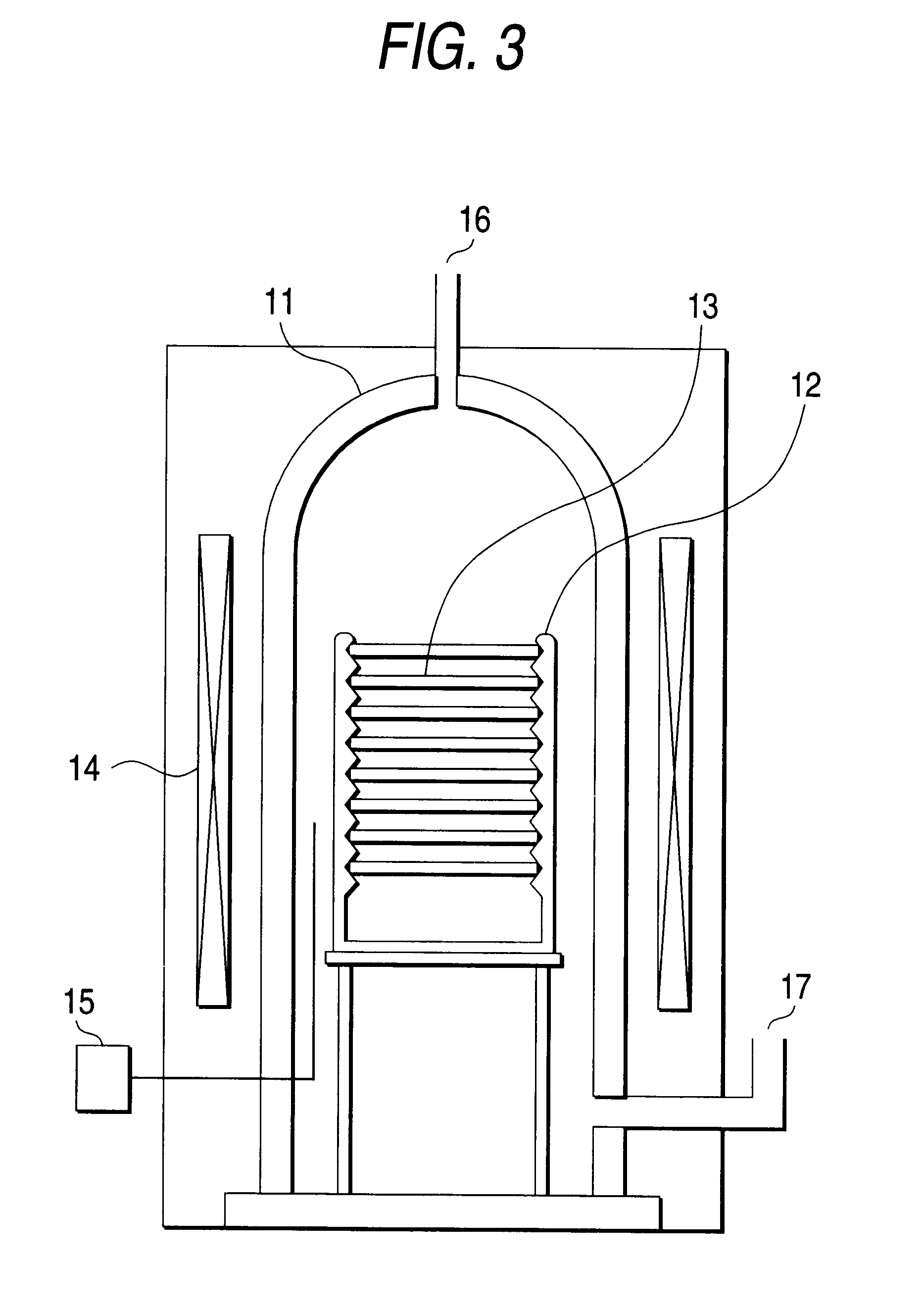
However, since the space of RF plasma formed on the target is larger than the space of plasma formed by DC sputter, RF sputter is accompanied by the problem that the amount of particles which come off the inner wall near the target and enter the film increases.
However, the sputtering rate of ion beam sputtering is lower than that of DC sputtering, resulting in reduced productivity.

Method used


Image

  • Phase shift mask blank, phase shift mask, and method for manufacturing the same
  • Phase shift mask blank, phase shift mask, and method for manufacturing the same
  • Phase shift mask blank, phase shift mask, and method for manufacturing the same

Examples


Embodiment Construction

, too, the film has larger surface roughness because of the higher pressure of film formation and is therefore inferior in acid resistance and alkali resistance as compared with embodiment 1. In Comparative Example 3 oxygen was introduced to increase the transmittance.

In Reference Example 1, although the surface roughness is small owing to the low pressure in film formation, the film stress is high due to the low heat treating temperature. Further, the film is slightly inferior in acid resistance, alkali resistance and irradiation resistance.

Where the metal content in the target exceeds 30 mol % as in Reference Example 2, the film has too low a transmittance and poor alkali resistance. Where the metal content is less than 5 mol % as in Reference Example 3, the target cannot maintain a stable discharge.

Incidentally, where the films of the foregoing embodiments and Examples were not subjected to the heat treatment, they had 1.3 to 2.5 times as much film stress as the respective values...


PUM

PropertyMeasurementUnit
Raaaaaaaaaaa
surface roughnessaaaaaaaaaa
Raaaaaaaaaaa

Abstract

An object of the present invention is to provide a half-tone phase shift mask blank and a half-tone phase shift mask of which a translucent film has improved acid resistance, alkali resistance and resistance to excimer laser irradiation while maintaining the internal stress of the film within an acceptable range for the intended use. To achieve the aforementioned object, the present invention provides a half-tone phase shift mask blank which comprises a transparent substrate having provided thereon a translucent film comprising at least one thin layer containing silicon and at least one of nitrogen and oxygen and which is to be exposed to light whose center wavelength is 248 nm or shorter, wherein said translucent film is dense such that it has a center-line surface roughness (Ra) of 0.3 nm or smaller.

Description

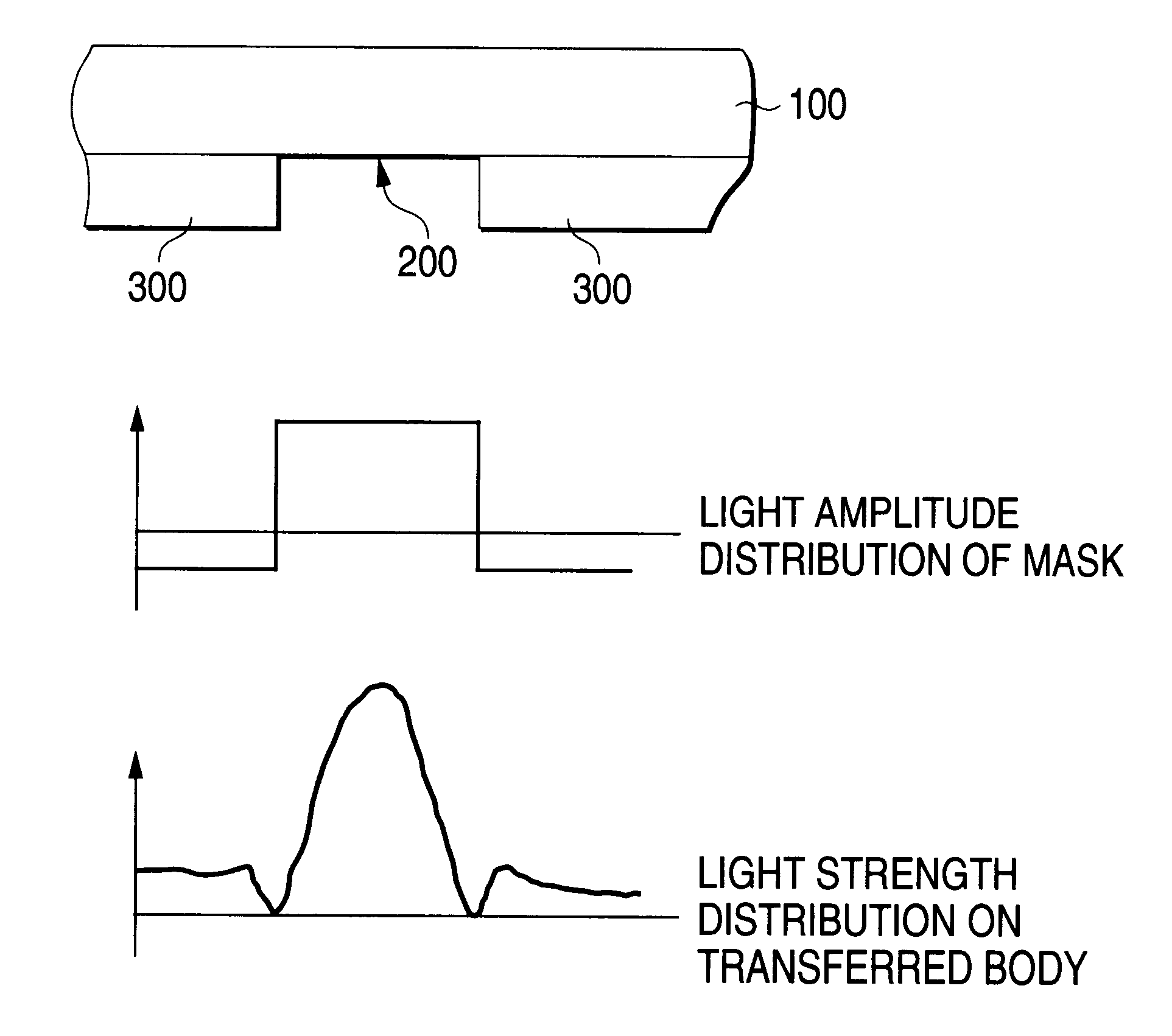
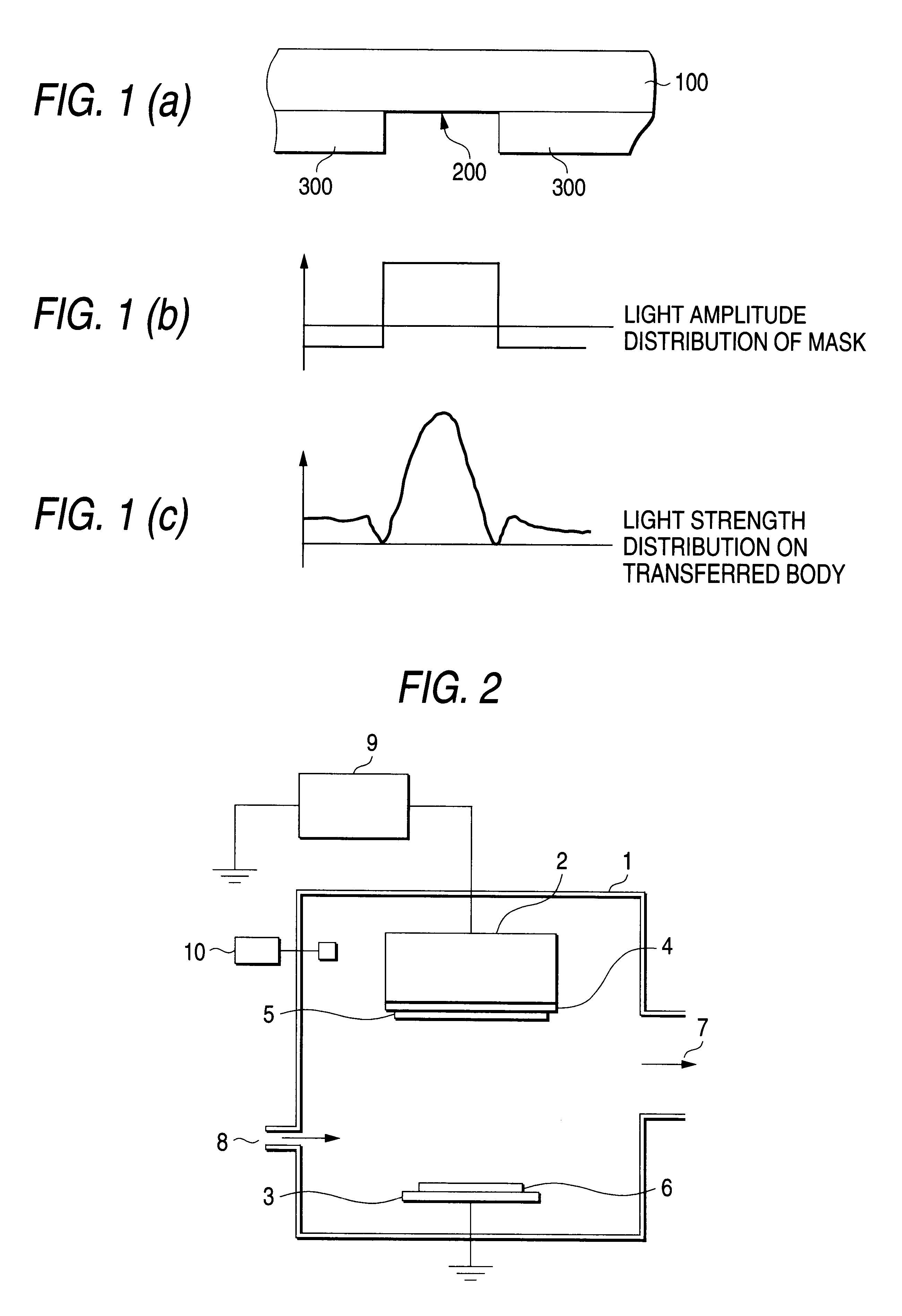
1. Field of the InventionThis invention relates to a phase shift mask. More particularly, it relates to an attenuating phase shift mask which attenuates light of exposure wavelength and is suitable for a KrF excimer laser and especially an ArF excimer laser and an F.sub.2 excimer laser, a blank therefor, and a process of fabricating the phase shift mask blank.2. Description of the Related ArtA high resolution and a depth of focus (DOF), which are significant characteristics required in photolithography, conflict with each other. It has been revealed that a resolution cannot be improved simply by increasing the numerical aperture of an optical aligner and shortening the exposure wavelength (see Semiconductor World, vol. 12 (1990) or Ohyo Buturi, vol. 60, No. 11(1991)).Under these circumstances, phase shift lithography has been attracting attention as a photolithographic technique of next generation and been partly introduced. Phase shift lithography is a technique for improving the r...

Claims


Application Information

Patent Timeline
Patent Type & Authority Patents(United States)
IPC IPC(8): G03F1/08G03F1/06G03F1/00G03F1/32G03F1/68H01L21/027
CPCG03F1/32G03F1/54
Inventor NOZAWA, OSAMUMITSUI, HIDEAKI
Owner HOYA CORP
Learn More