
Flat, bonded-electrode rechargeable electrochemical cell and method of making same

Inactive Publication Date: 2002-07-02
LITHIUM WERKS TECH BV
View PDF4 Cites 32 Cited by
  • Summary
  • Abstract
  • Description
  • Claims
  • Application Information

AI Technical Summary

Benefits of technology

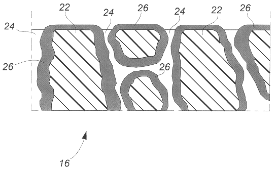
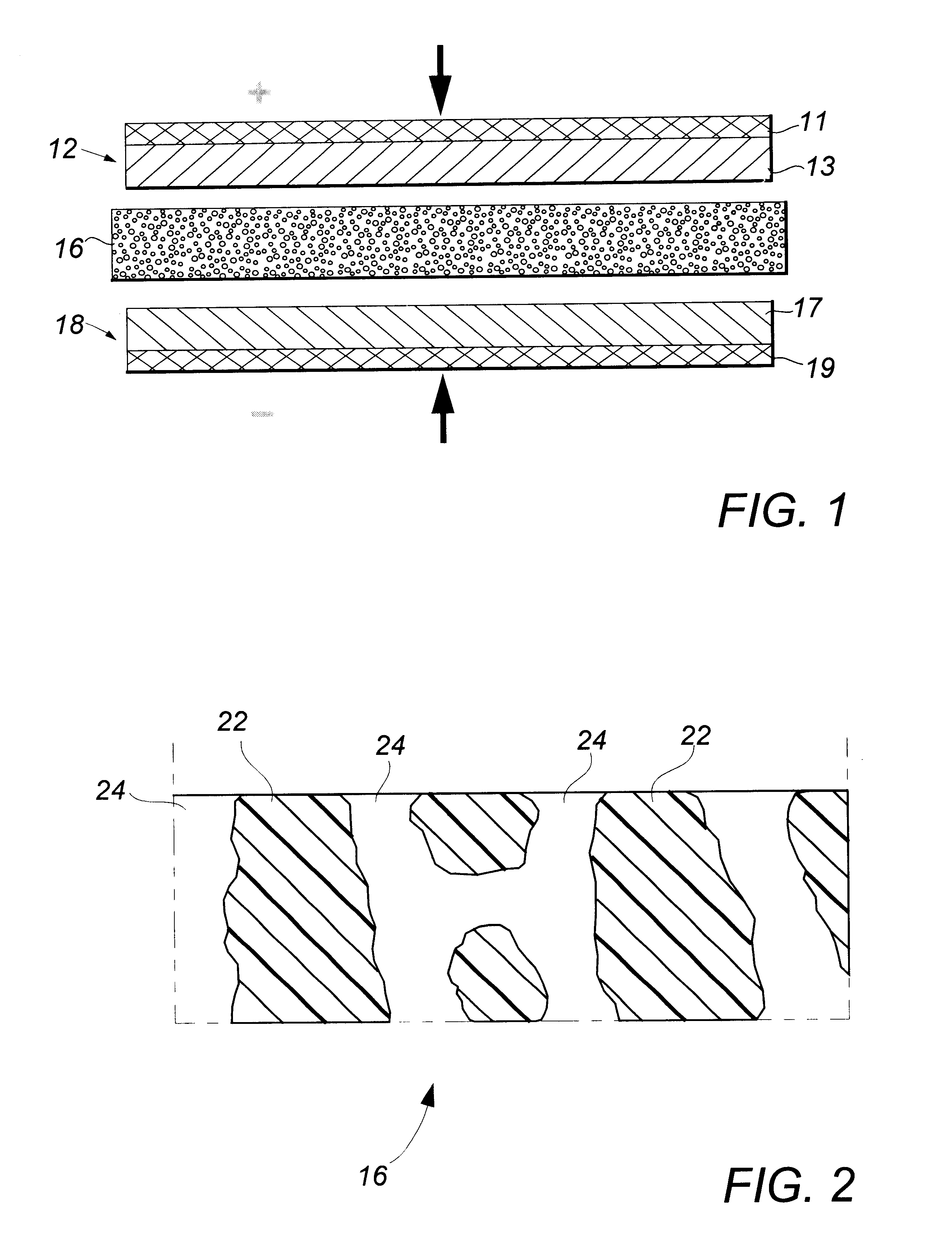
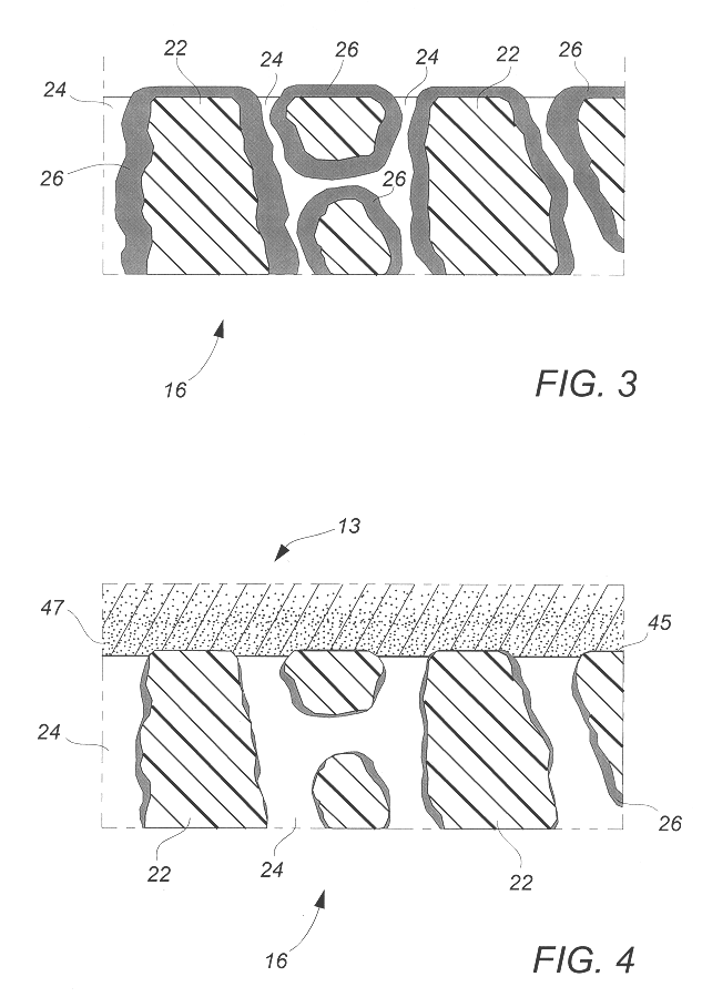
The present invention provides a simplified method of fabricating flat, high-capacity, high-discharge-rate, thermal-shutdown-protected electrochemical cells through the use of polymer matrix electrodes and economical, commercially available microporous polyolefin-separator membranes. More particularly, the present invention comprises a method for facilitating the lamination of electrochemical cell members without resort to additional polymeric adhesive compositions and at laminating temperatures and pressures which effect firm interfacial bonding between polymer matrix electrode members and an unmodified microporous separator membrane, yet are sufficiently low to avoid thermal and mechanical collapse or other occlusion of the porous membrane structure of the cell separator member.
The adhesive bond formed at the electrode and separator member interfaces as a result of the present invention was found to be surprisingly durable despite the fact that the normally abherent polyolefin surfaces of the microporous separator had not been previously subjected to expensive pre-coatings or polymeric adhesive compositions. Particularly noteworthy is the fact that the interfacial bonds of these cell members are able to survive extended exposure to solvent-based cell electrolyte compositions even at battery storage temperatures higher than about 80.degree. C. The surprising efficacy of separator-borne plasticizer alone in establishing strong interfacial cell member bonds provides a novel and simplified means for making long-sought-after, permanently bonded, flat rechargeable electrochemical battery cells with excellent performance characteristics and long operating life.

Problems solved by technology

Thus, in the event of a runaway cell heating episode, the porous polyolefin separator membrane becomes heated to a point of melting and its pore structure collapses, thereby interrupting the essential ionic conductivity within the cell and terminating the electrochemical reaction before a dangerous condition ensues.
However, these more flexible packages are decreasingly capable of achieving and maintaining the substantial physical pressures required to ensure the noted essential intimate interlayer contact throughout the electrochemical cell.
Although such laminated electrochemical cells and like energy storage devices have significantly advanced the art in miniaturized applications, the use of substantially non-porous polymeric matrices and membranes in their fabrication has deprived these devices of the desirable thermal shutdown feature achieved when using the microporous polyolefin separator membranes.
However, the low surface energy exhibited by the polyolefin membranes renders them highly abherent in nature and thus inhibits their strong, permanent adhesion to many polymeric electrode layer compositions, particularly within a reasonable temperature range which does not lead to melting and, thus, thermal collapse, of the porous structure of the polyolefin membranes.
However, it has generally been found that the application of such adhesive compositions, whether by overcoating, dipping, extrusion, or the like, significantly occludes or otherwise interferes with the porous structure of the polyolefin membranes and causes a deleterious decrease in electrolyte mobility and ionic conductivity.
Further, the addition of substantial amounts of such adhesive materials increases the proportion of non-reactive components in a cell, thereby detracting from the specific capacity of any resulting energy storage device.
This approach has proven to be insufficient in itself to enable satisfactory interfacial bonding between cell component layers at lamination temperatures below the critical level which results in collapse of separator porosity and its attendant loss of effective ionic conductivity and desirable shutdown capability.
However, this method suffers several problems with respect to assembly and cell performance.
First, it is extremely difficult to achieve within an enclosing package a sufficiently controlled and uniform pressure on a multi-ply folded or wound electrode / separator assembly to obtain an adequate strong bond between the respective layers, particularly in the fold region.
Second, very thin electrode layers and current collectors have to be used to prevent the electrodes and the current collectors from cracking and delamination.
Third, heating a liquid electrolyte activated electrochemical cell to a temperature sufficiently high to effect such bonding is deleterious to the cell's long-term electrochemical performance and often causes permanent physical and chemical damage to the multilayer foil packaging material and the foil feed-through tabs typically employed in the fabrication of such flat electrochemical cells.
It was apparently intended that the dispersed adhesive pattern would maintain an open-pored field within which electrolyte could freely reside; however, since NMP is a powerful solvent for PVdF and its copolymers, it significantly dissolves the binder polymer in the electrode and causes local filling of the micropores of the separator with a PVdF polymer, thus decreasing the effective ionic conductivity of the separator.
In addition, the applied adhesive polymer composition unproductively increases the cell mass, thus lowering its effective energy storage capability.
The problems mentioned above are even more pronounced in this method.

Method used


Image

  • Flat, bonded-electrode rechargeable electrochemical cell and method of making same
  • Flat, bonded-electrode rechargeable electrochemical cell and method of making same
  • Flat, bonded-electrode rechargeable electrochemical cell and method of making same

Examples


example i

Preparation of Polymeric Matrix Positive Electrode

A composition of 79 g of finely divided, commercial-grade LiCoO.sub.2, 6.5 g of PVdF-hexafluoropropylene (PVdF-HFP) copolymer (Kynar PowerFLEX LBG, Elf Atochem NA), 3.5 g of Super P conductive carbon (MMM Carbon, Belgium), 11 g of propylene carbonate (PC) plasticizer (Aldrich), and 90 g acetone (J. T. Baker) was mixed in an hermetically sealed vessel for 1 hour at about 45.degree. C. After additional homogenization in a laboratory blender, the resulting paste was cast on a polyester carrier film using a doctor-blade apparatus gapped at about 0.3 mm. The acetone was evaporated in a stream of warm air and the resulting self-supporting electrode composition layer was removed from the carrier. A section of the layer was laminated with a similarly sized section of expanded aluminum foil grid (MicroGrid, Delker Corp.), which had been pretreated as disclosed in U.S. Pat. No. 5,840,087, using a heated double-roll laminator at a temperature o...

example ii

Preparation of Polymeric Matrix Negative Electrode

A mixture of 72 g of MCMB 25-28 microbead mesophase artificial graphite (Osaka Gas Co., Japan), 7.5 g of PVdF-HFP copolymer (Kynar PowerFLEX LBG), 2.5 g of Super P conductive carbon, 18 g of PC plasticizer, and 70 g of acetone was processed as set forth in Example I. A section of the formed electrode membrane was laminated with a similarly sized section of expanded copper foil grid (MicroGrid, Delker Corp.) using a heated double-roll laminator at a temperature of about 135.degree. C. As alternative embodiments, the copper grid may be embedded between two electrode membranes or foil may be coated with an electrode paste in the manner described in Example I. An alternative negative electrode member prepared in the foregoing manner from a mixture of 90 g of MCMB 25-28 microbead graphite, 7 g of PVdF polymer, and 3 g of Super P carbon provided comparable results in the following cell fabrications.

example iii

Preparation of a Microporous Polyolefin Separator Member

A commercially available, three-layer, 25-.mu.m-thick Celgard 2300 microporous polyolefin separator membrane material was cut slightly larger in lateral dimensions than electrode members of Examples I and II to ensure complete electrical insulation between those members and was immersed for a few seconds in a 18% v / v solution of propylene carbonate (PC) plasticizer in methanol. Excess solution was allowed to drip from the sample which was then air-dried for several minutes to remove the methanol vehicle and deposit the PC on the surface and within the pores of the membrane without compromising the porous membrane structure.


PUM

PropertyMeasurementUnit
Temperatureaaaaaaaaaa
Pressureaaaaaaaaaa
Adhesivityaaaaaaaaaa

Abstract

A Li-ion battery cell comprising a polymeric matrix positive electrode layer member, a polymeric matrix negative electrode layer member, and an interposed microporous polyolefin separator layer member is laminated into a unitary, flexible cell structure by means of heat and pressure without necessity of applied interlayer adhesive. A volatile vehicle solution of a primary plasticizer for the electrode member polymer matrix is applied to the microporous separator member where it is absorbed into the porous structure. Evaporation of the volatile vehicle solvent deposits the plasticizer upon and within the pores of the separator member. During the lamination operation the plasticizer is forced into contact with the electrode member polymer where it softens the polymer into a thermoplastic adhesive in the region of the electrode / separator interface, thereby enabling the electrode polymer alone to form a strong bond to the separator upon cooling.

Description

The present invention generally relates to a method of making bonded multilayer, flat-plate electrochemical cell devices, such as rechargeable batteries and supercapacitors. More specifically, the invention provides a method for establishing persistent interfacial bonding between laminated planar electrode and microporous separator members utilized in such electrochemical devices.Widely deployed primary and secondary, rechargeable lithium-ion electrochemical cells are typical of electrochemical devices to which the present invention is directed. Such cells comprise layers, or membranes, of respective positive and negative electrode composition members assembled with a coextensive interposed separator member comprising a layer or membrane of electrically insulating, ion-transmissive material. This multilayer electrochemical cell structure is normally packaged with a mobile-ion electrolyte composition, usually in fluid state and situated in part in the separator member, in order to en...

Claims


Application Information

Patent Timeline
IPC IPC(8): B29C65/00B29C65/48B32B7/10H01M10/36H01M10/40H01M10/38H01M2/16H01M10/04H01M4/62H01M4/13H01M4/139H01M10/0525H01M10/0565H01M10/0585H01M50/417H01M50/489
CPCB29C66/45B29C66/727B32B7/10B32B37/00H01M4/13H01M4/139H01M4/622H01M10/0525H01M10/0565H01M10/0585H01M10/38B29C65/4895B29L2009/00B29L2031/3468B32B2305/026B32B2457/00H01M2/1653H01M10/04Y02E60/122B29C66/71B29C66/723B29C66/72321B29C66/1122Y02E60/10Y02P70/50H01M50/417H01M50/489B29K2033/20B29K2033/12B29K2027/16B29K2027/08B29K2027/06H01M10/14
Inventor GOZDZ, ANTONI S.
Owner LITHIUM WERKS TECH BV
Learn More