
Fuel injector for an internal combustion engine

a fuel injector and internal combustion engine technology, applied in the direction of fuel injection apparatus, spraying apparatus, feed system, etc., can solve the problems of unsuitable for further operation and other problems, and achieve the effect of increasing the temperature resistance of the nozzle body, improving the corrosion resistance of martensitic rustproof steel, and improving the corrosion resistan

Inactive Publication Date: 2001-01-02
ROBERT BOSCH GMBH
View PDF3 Cites 48 Cited by
  • Summary
  • Abstract
  • Description
  • Claims
  • Application Information

AI Technical Summary

Benefits of technology

This object is attained according to the invention with fuel injector of the type described at the beginning by virtue of the fact that the nozzle body is comprised of a rustproof martensitic steel, which is hardened by means of case hardening with nitrogen.The improvement of the corrosion resistance of martensitic rustproof steels by means of case hardening with nitrogen is drawn, for example, from DE 40 33 706 A1. In the heat treating process disclosed by this reference, the main idea is to increase the corrosion resistance.Based on a large number of trials, it has turned out that the heat treating process drawn from DE 40 33 706 A1 surprisingly can also be used to increase the temperature resistance of nozzle bodies. In particular, it has turned out that the above-described soft annealing of the nozzle body at high temperatures can be avoided through the use of a martensitic rustproof steel which has been hardened by means of case hardening with nitrogen.It is particularly advantageous in this connection that the injection openings are also hardened.Steels with the following composition can advantageously be considered as rustproof martensitic steels: <0.1, preferably 0.01 weight % C; from 0.03 to 0.3, preferably 0.1 weight % N; from 0.01 to 1.0, preferably 0.06 weight % Si; from 10.0 to 20.0 preferably 13.7 weight % Cr; <5.0, preferably 1.5 weight % Mo; <0.5, preferably 0 weight % Nb; <0.5, preferably 0.1 weight % V, and alloy additives for the suppression of .delta.-ferrite.In order to suppress the .delta.-ferrite formation, preferably alloy additives of the following composition are added: from 0.01 to 1.0, preferably 0.03 weight % Mn; <5.0, preferably 2.2 weight % Ni; <5.0, preferably 2.7 weight % Co.Up to now, no further information has been given with regard to the case hardening.The nozzle body is advantageously hardened by means of case hardening at a temperature of 1050 to 1200.degree. C., preferably 1100.degree. C., at a pressure of 0.5 to 10 bar, preferably at 3 bar, over a time period of 1 h to 30 h, preferably 4 h.Through such an embodiment of the nozzle body out of rustproof martensitic steel, which is hardened by means of case hardening with nitrogen as described above, not only are the corrosion and wear resistance significantly increased, but the retention of hardness and the red hardness are significantly increased as well.The advantages in so doing are as follows: there is an improved ease of machining of the unhardened initial material. The boundary layer hardening takes place with a higher degree of manufacturing reliability, which leads to a more uniform surface hardness and hardness penetration, particularly also in the bores that constitute the injection openings, without the occurrence of cleaning problems. Based on a simple manufacture, the fuel injectors can be manufactured not only in a technically simple manner, but also in a particularly inexpensive manner, wherein no distinction has to be drawn between fuel injectors for diesel injection systems and fuel injectors for gasoline injection systems.

Problems solved by technology

When diesel engines, namely those provided with a direct injection, are operated for motor braking, very high temperatures can be produced in the diesel fuel injectors, by means of which they can be "soft annealed" and as a result, can become unsuitable for further operation (wear, risk of fracture).
With the use of this type of fuel injectors in gasoline engines provided with direct injection systems, in addition to wear, problems also arise as a result of corrosion of the fuel injectors.

Method used


Image

  • Fuel injector for an internal combustion engine
  • Fuel injector for an internal combustion engine

Examples


Embodiment Construction

The invention is explained schematically below in conjunction with a fuel injector for a diesel engine. It goes without saying that the invention is not limited to fuel injectors for diesel engines, but also, extends to fuel injectors for gasoline direct injection systems.

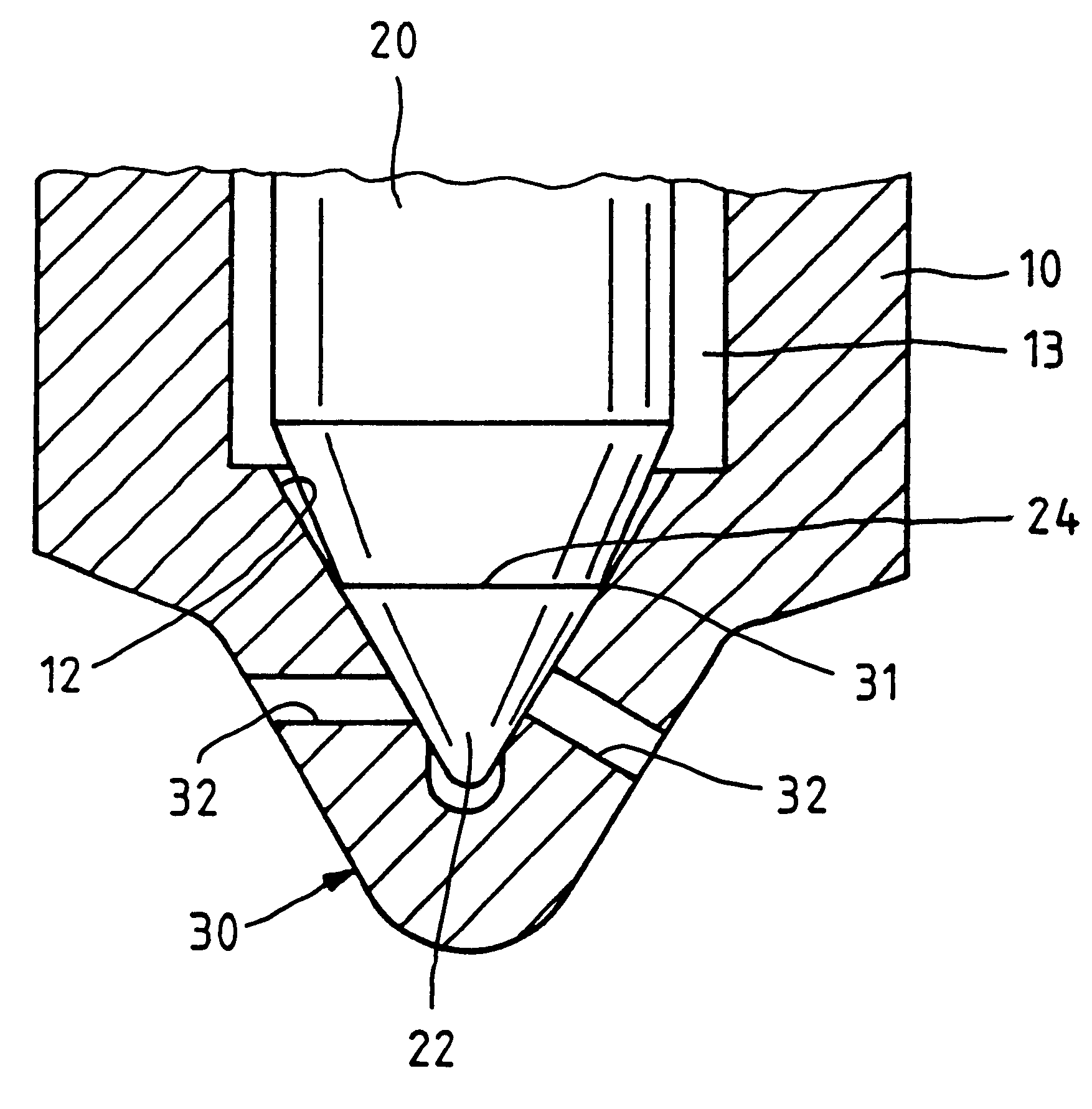
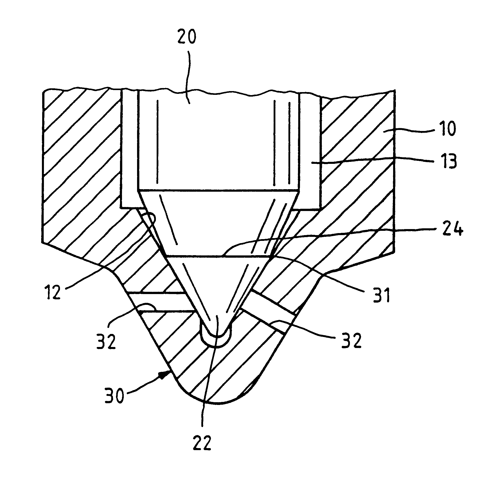
The fuel injector depicted in the sole FIGURE has a nozzle body 10 in which a valve needle 20 is movably supported. On its bottom end, the valve needle 20 has a conical sealing face 22, which comes into contact with a valve seat face 12 that is adapted to it and is therefore conical. The valve seat face 12 is formed on an inner wall region 31 of an end cup 30 of the nozzle body 10. A number of injection openings 32 lead from the valve seat face 12 and pass through the wall of the end cup 30 at an angle to the nozzle axis.

In carrying out the invention both the inner wall region 31, the valve seat face and an outer wall region of the nozzle body 10 are hardened with the use of nitrogen.

Between the valve needle 20 and...


PUM


Abstract

A fuel injector for internal combustion engines, with a nozzle body in which a valve needle with a sealing face is movably supported. The sealing face of the valve needle comes into contact with a valve seat face that is adapted to the sealing face and is formed on an inner wall region of an end cup of the nozzle body. At least one injection opening is provided in the valve seat face, wherein both the inner wall region with the valve seat face of the nozzle body disposed on it and an outer wall region are hardened. The nozzle body is comprised of a rustproof martensitic steel that is hardened by means of case hardening with nitrogen.

Description

PRIOR ARTThe invention relates to a fuel injector for internal combustion engines. A nozzle body includes a valve needle with a sealing face which is movably supported whose needle comes into contact with a sealing face adapted to the needle that is embodied in an inner wall region of an end cup of the nozzle body. At least one injection opening is provided in this sealing face, wherein both the inner wall region, with the sealing face of the nozzle body disposed on it, and its outer wall region are hardened.This kind of fuel injector for internal combustion engines is drawn, for example, from EP 0 233 190 B1. In that instance, the inner wall region of the end cup provided with the valve seat face, through boundary layer hardening, is provided with a greater hardness than the outer wall region and the central boundary region disposed between the valve seat face and the opposing outer wall region.The nozzle body of these fuel injectors is comprised of case hardened steel, which is va...

Claims


Application Information

Patent Timeline
IPC IPC(8): F02M61/00F02M61/16F02M61/18
CPCF02M61/166F02M61/18Y10S239/19
Inventor SEITTER, MAXMUEHLEDER, FRIEDRICH
Owner ROBERT BOSCH GMBH
Learn More