
Ceramic coating for foundry core

Pending Publication Date: 2021-09-30
COMMISSARIAT A LENERGIE ATOMIQUE ET AUX ENERGIES ALTERNATIVES +1
View PDF1 Cites 0 Cited by
  • Summary
  • Abstract
  • Description
  • Claims
  • Application Information

AI Technical Summary

Benefits of technology

The aim of this patent is to provide a solution that can adapt to different geometries and is easy to achieve, in order to limit costs and maximize production volumes.

Problems solved by technology

This very significant oxidation of molybdenum or TZM parts leads to a significant loss of mass and a rapid degradation of mechanical properties.
An interdiffusion of the refractory alloy elements from the core to the superalloy can lead to a modification of the mechanical properties of the superalloy, and thus to a degradation of the performance of the part obtained.
Due to the marked difference in density between polymers (from 1 to 1.2 g·cm−1) and ceramic materials (2-3 g·cm−1), a linear shrinkage of more than 30% generally leads to extensive cracking and high porosity in the ceramic coating.
The appearance of cracks in the coating is particularly detrimental to its effectiveness.
In particular, any through-crack in the coating brings the refractory alloy substrate into contact with the oxidizing atmosphere and renders the oxidation protection of the coating null and void.

Method used


Image

  • Ceramic coating for foundry core
  • Ceramic coating for foundry core

Examples


example embodiment

of a Coating

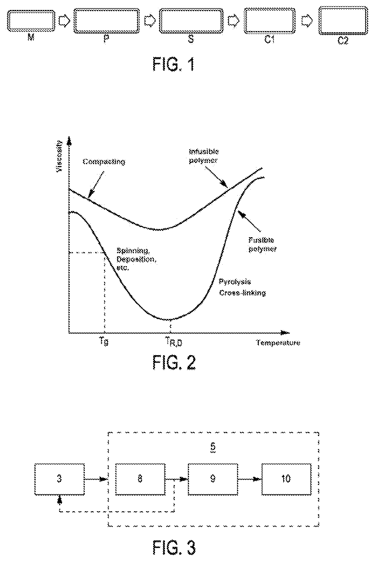
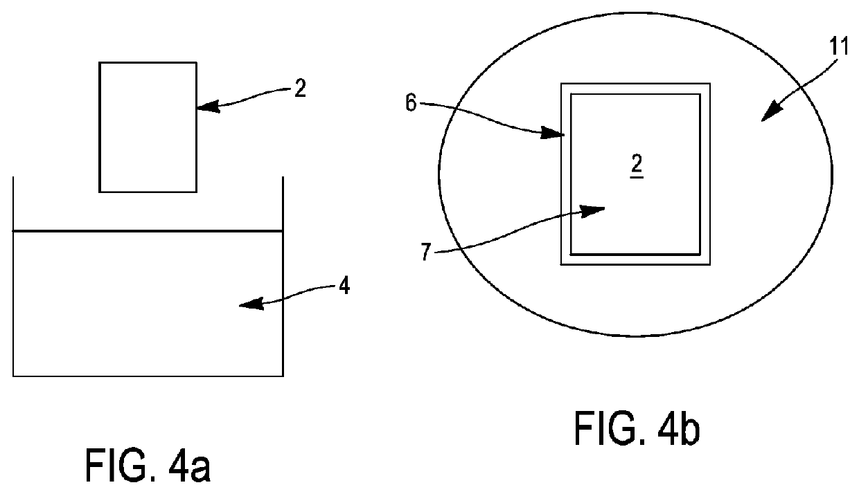
[0172]An example of the treatment composition 4 for dip coating 3 comprises:[0173]A mass proportion comprised between 45% and 70% of Terpineol solvent, preferentially between 50% and 65%, for example 53%,[0174]A mass proportion comprised between 15% and 40% of SILRES MK® (polysiloxane preceramic polymer, having a theoretical conversion rate of ceramic to silicon dioxide SiO2 or to silicon oxycarbide Si—O—C of 80% by mass), preferentially between 20% and 35%, for example 27%,[0175]A mass proportion comprised between 10% and 30% of fine silica (fine is understood to mean for example that 10% of the grains have a diameter less than 3 microns, 50% of the grains have a diameter less than 11 microns, and 10% of the grains have a diameter greater than 38 microns), preferentially between 15% and 25%, for example 20%.

[0176]In a first step the dissolution of the preceramic polymer in Terpineol is carried out at 60° C. under magnetic stirring in a beaker for at least 30 minutes. Th...


PUM

PropertyMeasurementUnit
Lengthaaaaaaaaaa
Fractionaaaaaaaaaa
Fractionaaaaaaaaaa

Abstract

A process for coating a refractory alloy part is provided and includes coating an area of a refractory alloy part by means of a treatment composition including a type of preceramic polymer and a solvent, and heat treating the part coated with the treatment composition. The heat treating partially converts the preceramic polymer and forms a ceramic coating obtained by conversion, the ceramic coating protecting the refractory alloy from oxidation. The treatment composition also includes active fillers to form an alloy coating on a surface of the part by solid diffusion in addition to the ceramic coating obtained by conversion, and the alloy coating generates a protective oxide layer when subjected to oxidizing conditions.

Description

GENERAL TECHNICAL FIELD AND PRIOR ART[0001]The invention relates to the field of protective coatings for mechanical parts, more precisely coatings for foundry cores.[0002]During a foundry manufacturing process, cores are conventionally arranged in foundry molds, prior to the injection of the liquid metal, so as to create one or more cavities or recesses in the parts that will be made during the manufacturing process.[0003]These cores are conventionally made of refractory ceramics.[0004]Alternatively, it is known to use foundry cores made of refractory alloys to replace or complement the ceramic cores conventionally used.[0005]These refractory alloy materials, typically molybdenum alloys, must be coated with a protective layer to preserve their mechanical characteristics, in particular in the presence of very high temperatures encountered for example during the manufacturing process of superalloy blades for gas turbines.[0006]In the case of investment casting processes, shells made o...

Claims


Application Information

Patent Timeline
IPC IPC(8): B22C9/12B22C3/00B22C9/10C09D4/00C04B35/56
CPCB22C9/12B22C3/00C04B2111/00568C09D4/00C04B35/5603B22C9/10B22C1/00B22C9/101
Inventor BECHELANY, MIRNAJAQUET, VIRGINIESABOUNDJI, AMARSOULIER, MATHIEUBOIDOT, MATHIEULAUCOURNET, RICHARD
Owner COMMISSARIAT A LENERGIE ATOMIQUE ET AUX ENERGIES ALTERNATIVES
Learn More