
Fuel metering unit for an aircraft engine

a fuel metering unit and aircraft engine technology, applied in the field of aeronautics, can solve the problems of premature death of the engine, cost and difficulty, and cut off the engine before it damages itself, so as to facilitate the certification strategy of the system, increase the performance of the engine, and limit the cost and physical impa

Pending Publication Date: 2022-01-13
SN DETUDE & DE CONSTR DE MOTEURS DAVIATION S N E C M A
View PDF2 Cites 0 Cited by
  • Summary
  • Abstract
  • Description
  • Claims
  • Application Information

AI Technical Summary

Benefits of technology

The invention helps to integrate an electronic board into a conventional metering unit by adding engine protection functions. This makes it easier to certify the system and improves the engine's performance by improving metering accuracy. Overall, the invention helps to increase efficiency while reducing costs and physical impacts.

Problems solved by technology

However, the behavior of an engine computer (control computer, also called FADEC for “Full Authority Digital Engine Control,” and more generally called an EEC, for “Electronic Engine Controller”) in the event of overheating or of fire is difficult to predict, which causes engine manufacturers to consider the worst case assumption for the certification of computers (by the certification authorities for aeronautical equipment).
Thus, the certification constraints impose not undergoing a simple electrical or electronic which could cause a hazardous event.
In the contrary case, if a “non-clean death” is considered, the overspeed protection function therefore “dies” prematurely, leaving the control function sole master on board.
The worst scenario would then be an erroneous command of the control system to a member controlling the engine, for example an erroneous position command to an actuator of a fuel metering unit leading to an overspeed condition of the engine in which the overspeed protection function could not accommodate the breakdown and consequently cut off the engine before it damages itself.
For this reason, they are very costly and difficult to obtain, and subject to early obsolescence.
. . housing, harness, supports) are considered to be great and are manifested in particular by an increase in the specific fuel consumption.
Moreover, the development costs of an electronic aircraft computer are very high; an architecture comprising two computers developed independently is therefore particularly costly.
This publication does not disclose a detection strategy allowing discriminating overheating not linked to an ignition start.
On the other hand, the solution of this publication does not allow ensuring a sufficient thermal margin, considering thermal inertia, to ensure a “clean death” of the control computer.
Consequently, considering the current state of the art, there exists no very satisfying solution for a fuel feed control system having an overspeed protection function for an aircraft engine, not penalizing mass and installation cost, and allowing satisfying the certification constraints for accommodating a degraded operation mode of the engine such as in response to a case of fire.

Method used


Image

  • Fuel metering unit for an aircraft engine
  • Fuel metering unit for an aircraft engine
  • Fuel metering unit for an aircraft engine

Examples


first embodiment

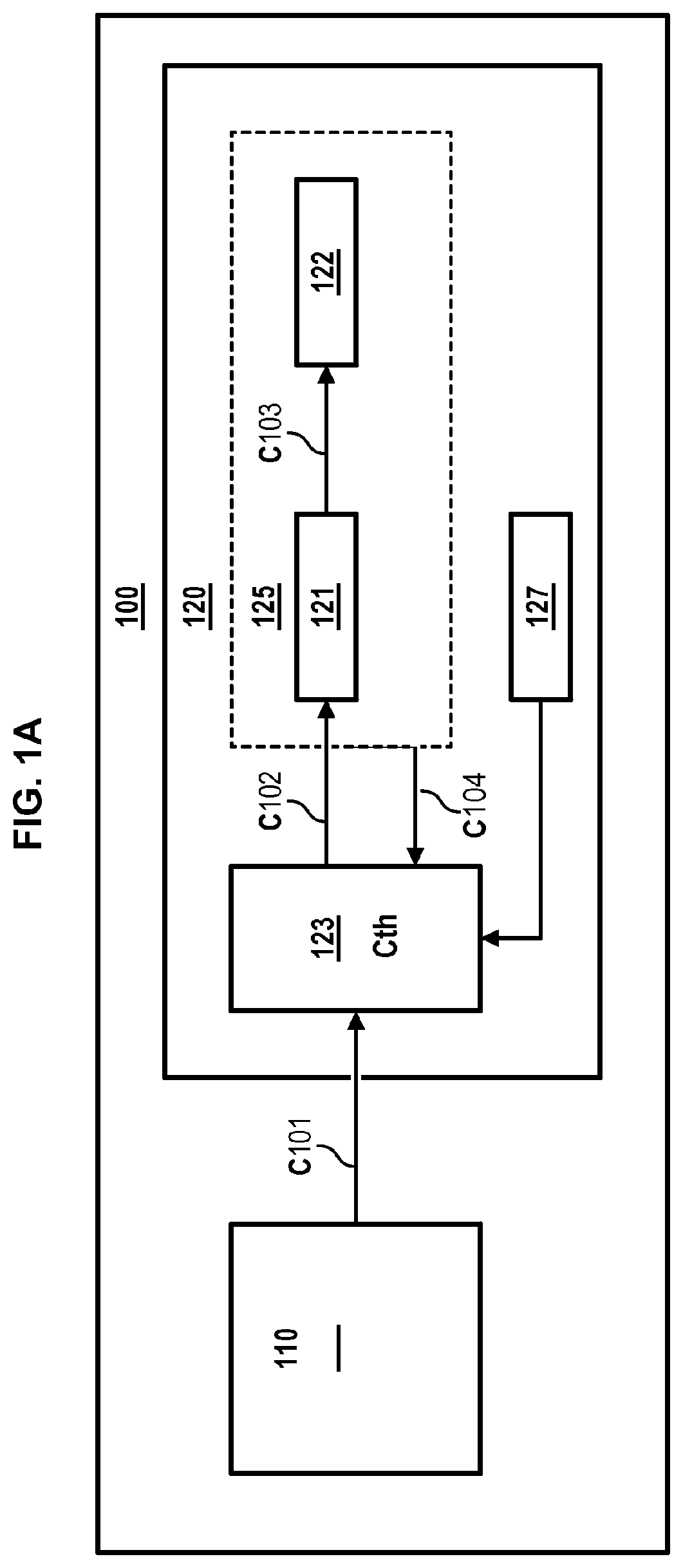
[0048]FIG. 1A illustrates a control and protection system 100 of an aircraft engine, implemented by a distributed architecture, according to a first embodiment.

[0049]Thus, the system 100 comprises an engine control computer 110 which generates a fuel mass flow rate setpoint C101 to provide the thrust demanded by the aircraft in real time. This setpoint C101 is then transmitted to an electro-hydromechanical metering unit 120 which carries out the fuel metering.

[0050]More precisely, the setpoint C101 is transmitted to a power control computer 123 of the electro-hydromechanical metering unit 120.

[0051]The control computer 123 determines, depending on the flow rate setpoint C101, a theoretical position setpoint Cth of a fuel metering member 125 (of the FMV type for example) of the electro-hydromechanical metering unit 120.

[0052]Depending on the movement setpoint Cth, the control computer 123 transmits an electrical control setpoint C102 to a servovalve 121 (of the EHSV for “Electro-Hydr...

second embodiment

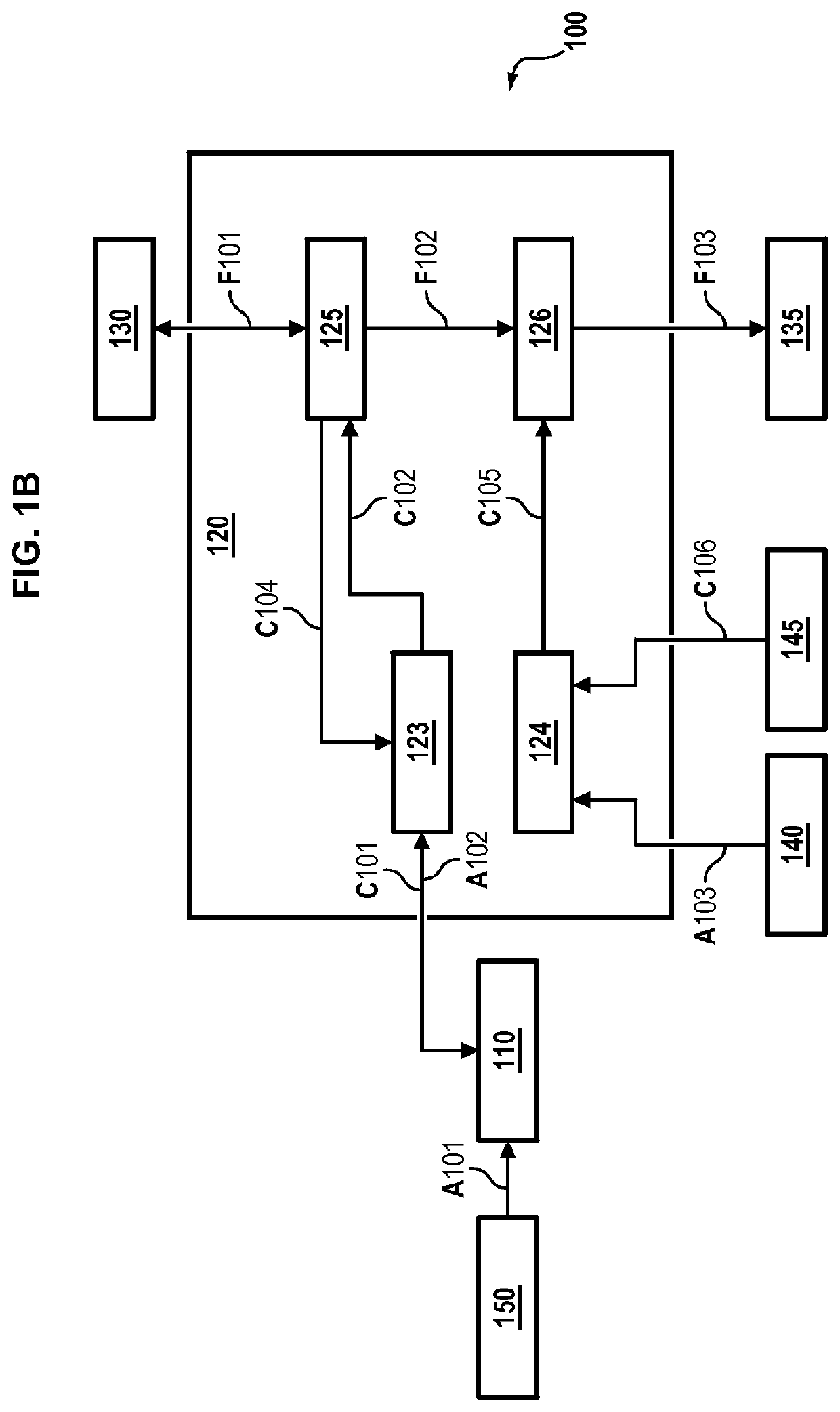
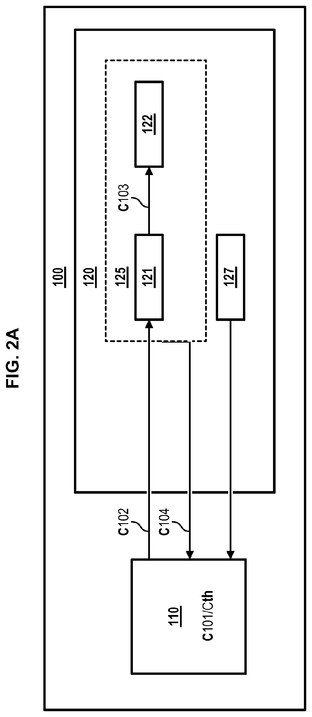
[0080]FIG. 1B illustrates a sub-system 200 for controlling the control and protection system 100 according to a second embodiment.

[0081]In the electronic fuel metering unit 120 are located the hydraulic servovalve 121 and the actuator 122 (FMV), as well as its position sensor.

[0082]However, unlike the first embodiment, certain of the functions linked to fuel metering are implemented in the engine control computer 110: the generation of the flow rate setpoint, the corrector network, the generation of the position command, as well as the acquisition of at least position sensor which provides information regarding the position of the movable slide of the FMV.

[0083]As in the first embodiment, the control and protection system 100 can also comprise a flowmeter as described in the first embodiment.

[0084]The flowmeter allows measuring the mass flow of fuel originating in the electro-hydromechanical metering unit 120. Unlike the first embodiment, this measurement is then communicated to the...


PUM


Abstract

The present invention relates to a fuel metering unit for an aircraft engine, comprising: —a metering member configured to receive a position control signal and to meter the feed of fuel to the engine depending on said position control; —a cutting member configured to cut the feed of fuel to the engine; and characterized in that the fuel metering unit also has a computer for protecting and cutting the engine, said protecting and cutting computer being configured to—detect an overspeeding state of the engine speed and—in response to the detection of an overspeeding state, to transmit a cutting control signal to a cutting control member contained in the cutting member.

Description

FIELD OF THE INVENTION[0001]The present invention relates to the general field of aeronautics.[0002]It relates more particularly to the field of fuel feed control systems for an aircraft engine. This engine is, for example, a turbomachine such as a turbojet.PRIOR ART[0003]In known fashion, the control system of an aircraft engine comprises a main electronic computer which appears in the form of a housing enclosing one or a plurality of electronic boards assigned to provide various functions.[0004]In current engines, the engine control system is generally responsible for controlling a fuel metering unit, corresponding to a hydromechanical block commonly called FMU (“fuel metering unit”).[0005]The hydromechanical block provided several functions in common. It provides, through a metering member, the metering of the fuel, i.e. the translation of the required fuel flow rate information within the total fuel flow rate fed by the pumping system, which results from a need prescribed by a c...

Claims


Application Information

Patent Timeline
Patent Type & Authority Applications(United States)
IPC IPC(8): F02C7/22
CPCF02C7/22F05D2240/35F05D2220/323F02C9/263F02C9/28F02C9/46F05D2270/021F05D2270/3032F05D2270/304Y02T50/60
Inventor FOIRET, GUILHEM ALCIDE AUGUSTEJOUDAREFF, ARNAUD BERNARD CLÉMENT THOMAS
Owner SN DETUDE & DE CONSTR DE MOTEURS DAVIATION S N E C M A
Learn More