
Underbody for the co-installation of an electric engine and a heat engine

a technology for electric engines and heat engines, which is applied in the direction of gas pressure propulsion mounting, propulsion parts, transportation and packaging, etc., to achieve the effect of limiting simplicity, cost and flexibility, and facilitating the adaptation of the length of the vehicl

Active Publication Date: 2019-02-26
RENAULT SA
View PDF16 Cites 1 Cited by
  • Summary
  • Abstract
  • Description
  • Claims
  • Application Information

AI Technical Summary

Benefits of technology

[0008]In particular, it is an object of the invention to provide such a central underbody part and a structural body which allows the alternative installation of either an electric motor or an internal combustion engine for the same platform, and which facilitates the adaptation in length of the vehicle, while limiting the simplicity, costs and flexibility.

Problems solved by technology

For electric vehicles however, the underbodies are dedicated solely to this type of motor and cannot be used with an internal combustion engine.

Method used


Image

  • Underbody for the co-installation of an electric engine and a heat engine
  • Underbody for the co-installation of an electric engine and a heat engine
  • Underbody for the co-installation of an electric engine and a heat engine

Examples


Embodiment Construction

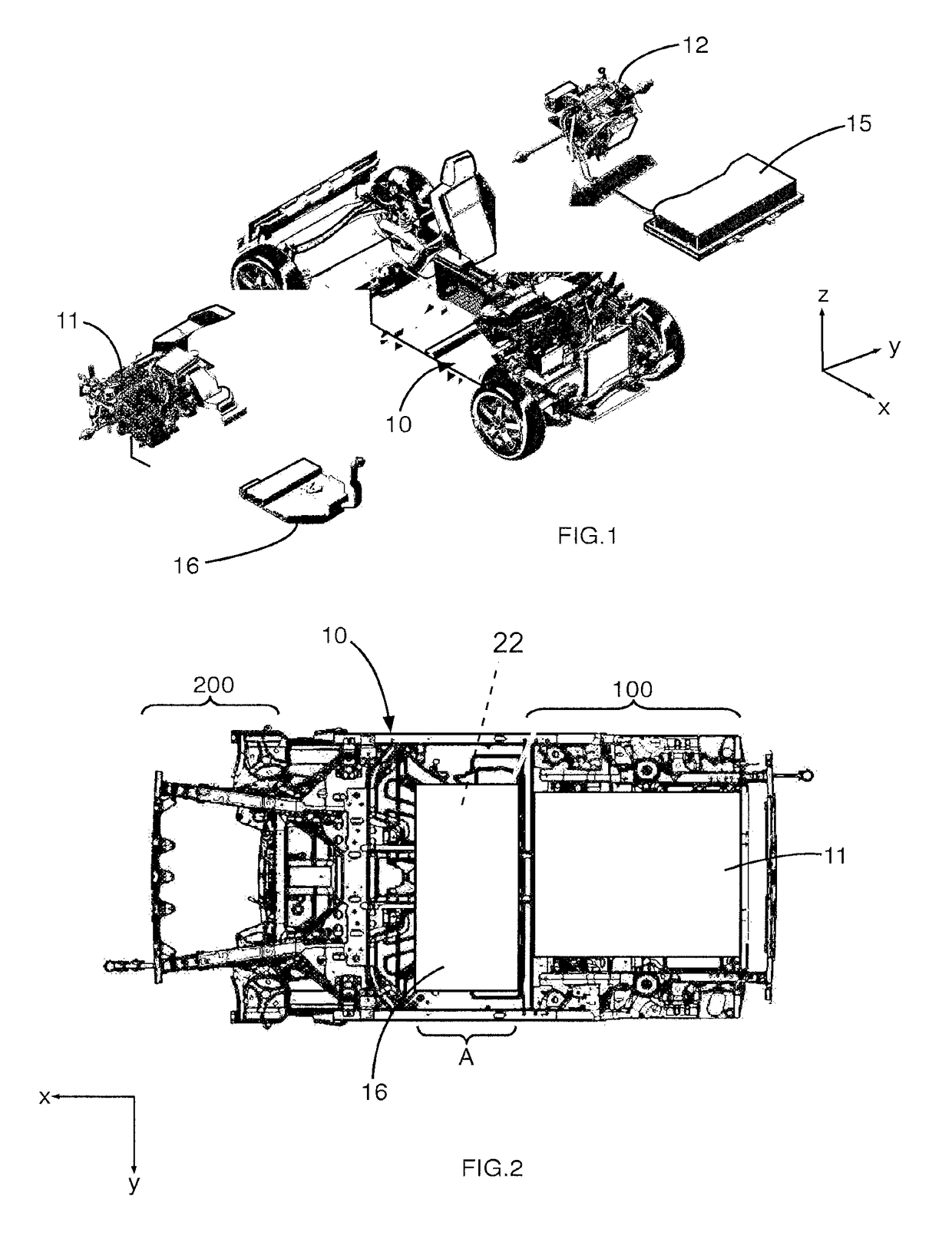
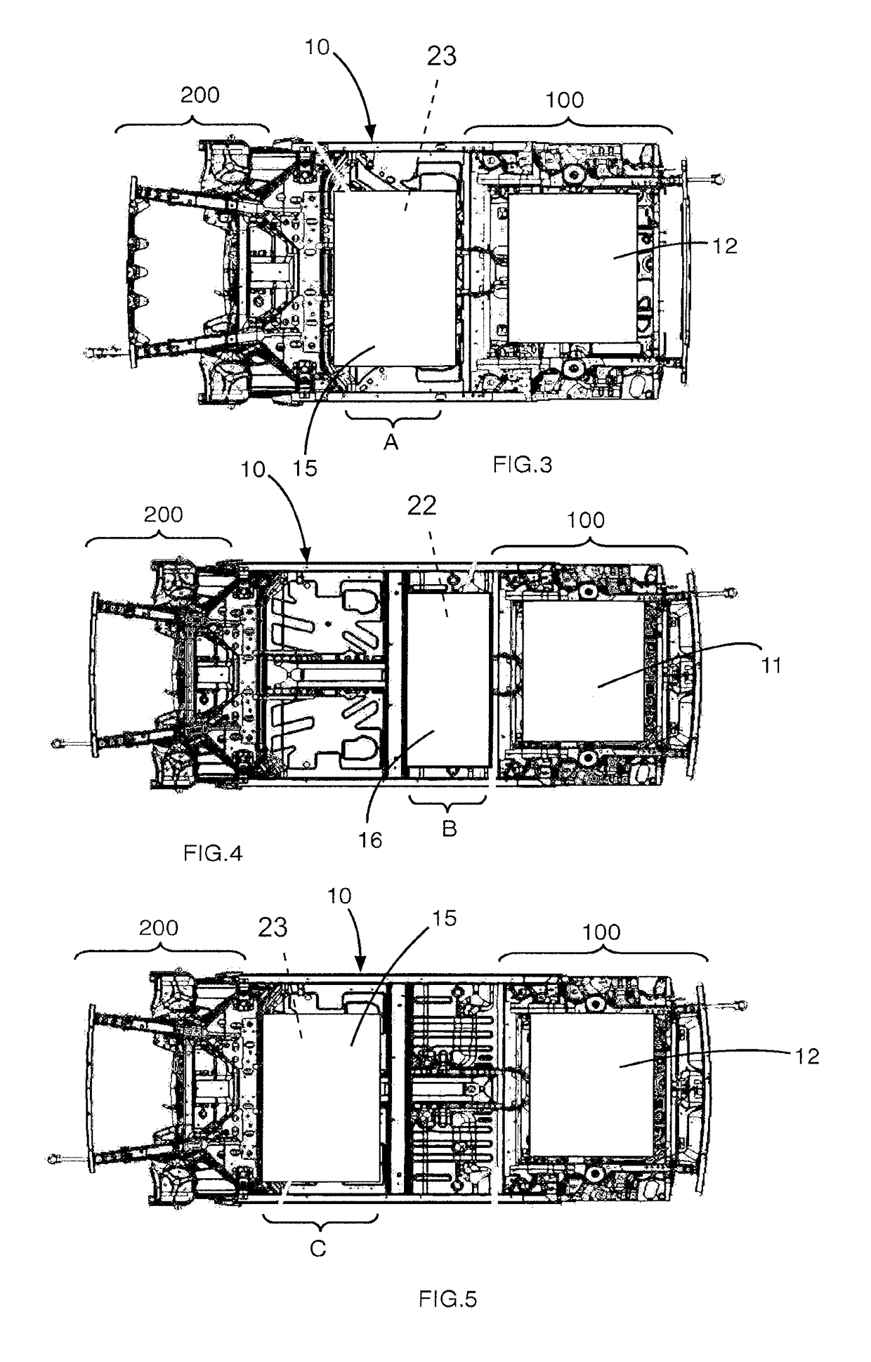
[0033]The description below is given with reference to an orthonormal reference system (X, Y, Z) conventionally associated with a motor vehicle, in which X is the front-rear, horizontal, longitudinal direction of the vehicle; Y is the right-left, transverse direction which is horizontal and perpendicular to X; and Z is the vertical direction, perpendicular to both directions X and Y. These directions may be considered as linked to the structural body of the vehicle and hence also to the motor vehicle.

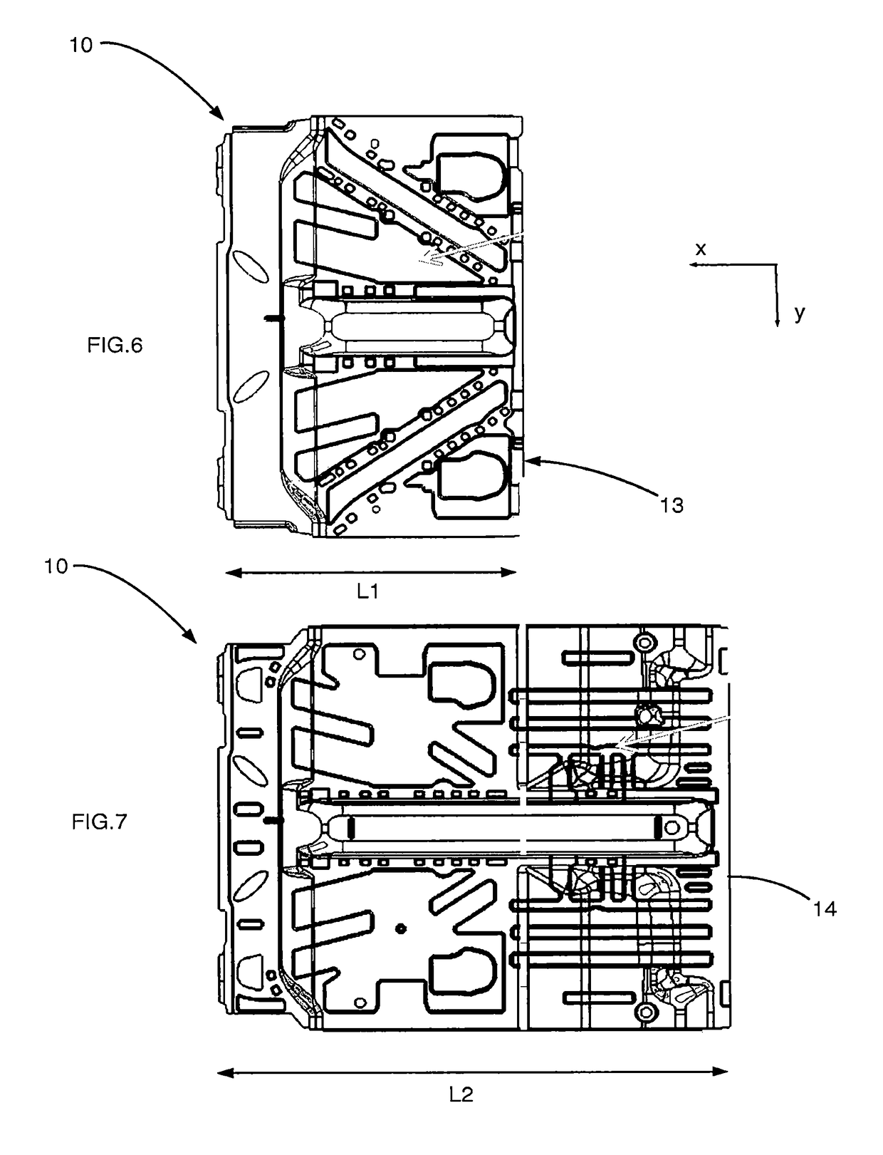
[0034]The central underbody part 10 of the structural body of the motor vehicle, visible in particular on FIGS. 2 to 7 and intended to delimit the lower part of a vehicle cab, comprises:[0035]a set of first interface elements allowing mounting, on the central underbody part 10, of components of the first type associated with the function of an internal combustion drive engine 11 of the vehicle and intended to be mounted on a rear structural part 100 of the structural body firmly attache...


PUM


Abstract

A range includes at least two different motor vehicles with a structural body having a central underbody part delimiting a lower part of a cab. The central underbody part of the first vehicle receives two seats. The central underbody part of the second vehicle receives four seats. Each central underbody part includes first interface elements allowing mounting thereon of components associated with the function of an internal combustion drive engine mounted on a rear structural part of the structural body which is firmly attached to the central underbody part. Each central underbody part also includes second interface elements allowing mounting thereon of components associated with the function of an electric drive motor to be mounted on the rear structural part. A rear edge of the central underbody part of each vehicle is equipped with a same interface element for connection to the rear structural part of the structural body.

Description

TECHNICAL FIELD OF THE INVENTION[0001]The invention concerns a central underbody part of the structural body of a motor vehicle, intended to delimit the lower part of a vehicle cab and to be interposed between the front and rear structural parts.[0002]The object of the invention is also a structural body of a motor vehicle comprising such a central underbody part.PRIOR ART[0003]At present, underbodies of motor vehicles are dedicated to a given engine type selected from an internal combustion (heat) engine or an electric motor. For the same vehicle platform, an underbody associated with the internal combustion engine and another different underbody associated with the electric motor must therefore be designed and produced.[0004]For internal combustion engines installed in a front structural unit of the body, the fuel tank is installed below the floor of the rear structural unit. The floor of the central underbody part is a floor situated at a height at which it extends below the inne...

Claims


Application Information

Patent Timeline
Patent Type & Authority Patents(United States)
IPC IPC(8): B60K6/40B62D25/20B62D21/15B62D63/02
CPCB60K6/40B62D21/152B62D25/20B62D25/2027B62D63/025B62D25/2018Y10S903/951
Inventor HLUBINA, THIERRYGAUMONT, HERVE
Owner RENAULT SA
Learn More