
Filter having a filter cartridge, and corresponding filter cartridge

a filter and cartridge technology, applied in the direction of filtration separation, membrane technology, separation process, etc., can solve the problems of assembly generation of high maintenance cost, closed element in sealing area fouled and remaining fouled,

Active Publication Date: 2017-02-21
CUMMINS FILTRATION IP INC
View PDF12 Cites 1 Cited by
  • Summary
  • Abstract
  • Description
  • Claims
  • Application Information

AI Technical Summary

Benefits of technology

[0010]More specifically, it is a goal of the disclosure to provide a filter assembly that performs well while at the same time limiting the cost of maintaining and replacing the filter cartridge.
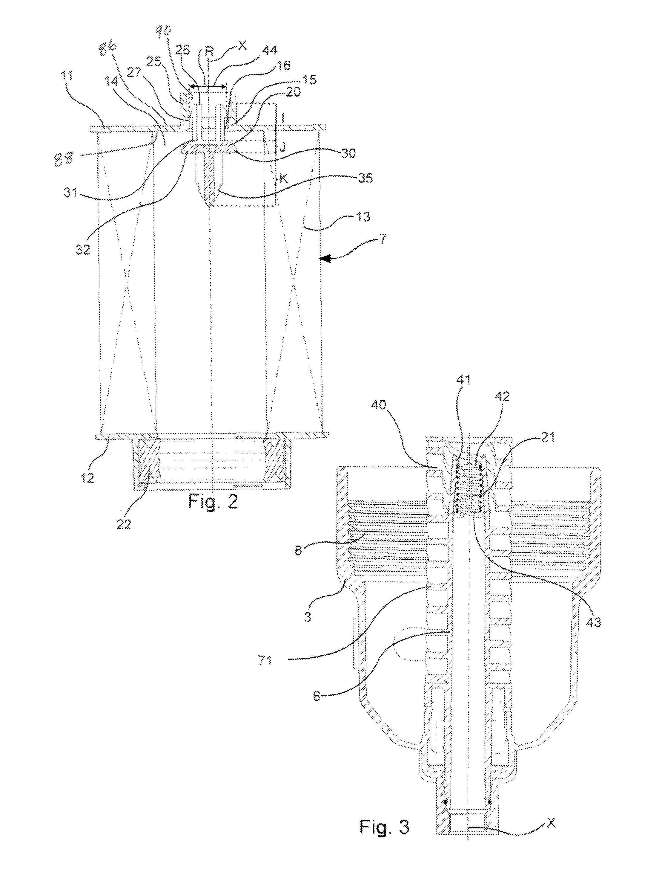
[0024]Another advantage of the disclosure is that modifying the dimensions of the closure element alone can make it possible to modify the threshold pressure for opening the valve formed by the valve seat, the closure element and the return member, according to the user's wishes, without in any way affecting the permanent part of the filter assembly. A same filter assembly will thus be modified in its performance, it being necessary then to modify not the permanent part but only the detachable part of the filter assembly, namely the filter cartridge.

Problems solved by technology

One drawback of such a system is that the closure element in the sealing area is fouled and remains fouled, even with the changing of the filter cartridge.
Such assemblies generate high maintenance costs.

Method used


Image

  • Filter having a filter cartridge, and corresponding filter cartridge
  • Filter having a filter cartridge, and corresponding filter cartridge
  • Filter having a filter cartridge, and corresponding filter cartridge

Examples


Embodiment Construction

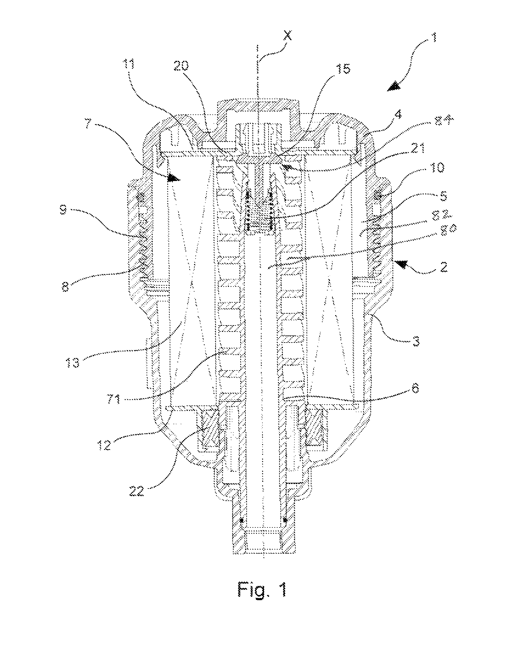
[0053]FIG. 1 shows a filter assembly 1 for a fluid flowing in a hydraulic motor or apparatus. This filter assembly 1 comprises a filter body 2 comprising a vessel 3 and a cover 4. The filter body 2 demarcates a volume 5 within which the filter assembly 1 comprises a tube 6, in this example a center tube. The filter assembly 1 also has a filter cartridge 7 shown isolatedly in FIG. 2.

[0054]The vessel 3 is provided with an internal thread 8 and the cover 4 is provided with an external thread 9 that can be screwed onto the internal thread 8 of the vessel 3 so as to close the filter assembly 1. The tight sealing of the filter assembly 1 is furthermore ensured by at least one ring seal 10, inserted between the cover 4 and the vessel 3. It is thus easy to unscrew the cover 4 and the vessel 3 from the filter body 2 in order to extract the filter cartridge 7, when this cartridge is worn out, to replace it with a new filter cartridge 7.

[0055]The filter cartridge 7 has a first flange 11 called...


PUM

PropertyMeasurementUnit
areaaaaaaaaaaa
pressureaaaaaaaaaa
threshold pressureaaaaaaaaaa

Abstract

A filter assembly includes a filter body, a removable filter cartridge, and a bypass valve with incinerable and non-incinerable portions. The bypass valve includes a valve seat and a movable valve closure element removable with the removable filter cartridge and incinerable. The bypass valve includes a return member remaining in the filter body. A method is provided for controlling bypass valve-opening threshold pressure.

Description

CROSS-REFERENCE TO RELATED APPLICATION[0001]This application is a continuation-in-part of International Patent Application No. PCT / FR2012 / 050705, filed Mar. 30, 2012, incorporated herein by reference.PARENT INTERNATIONAL APPLICATION[0002]The following is an English translation in accordance with the above noted parent international application and the present disclosure.FIELD OF DISCLOSURE[0003]The disclosure relates to the field of the designing and making of filter assemblies used to filter fluids, including fluids flowing in hydraulic motors or apparatuses.[0004]Such filtering assemblies consist of a filter element, comprising a vessel and a cover, within which there is disposed a filter cartridge comprising a filtering medium, generally cylindrical in shape and surrounding a tubular hollow space, the filtering medium being made for example of paper, cardboard or again felt or another porous material, such as a synthetic non-woven material. The filter cartridge also has two end p...

Claims


Application Information

Patent Timeline
Patent Type & Authority Patents(United States)
IPC IPC(8): B01D35/147B01D35/16
CPCB01D35/1475B01D35/147B01D35/16B01D2201/0415B01D2201/162B01D2201/295B01D2201/305B01D2201/316B01D2201/34B01D35/30
Inventor MALGORN, GERARDBAGCI, ISMAIL
Owner CUMMINS FILTRATION IP INC
Learn More