Method of manufacturing a building element and a building element
a manufacturing method and building element technology, applied in the field of building element manufacturing, can solve the problems of increasing the risk of mechanical interlocking, bridging or ratholing, and difficult to scatter wood powder evenly across the substrate without obtaining naked areas without, and achieve the effect of increasing the flowability
- Summary
- Abstract
- Description
- Claims
- Application Information
AI Technical Summary
Benefits of technology
Problems solved by technology
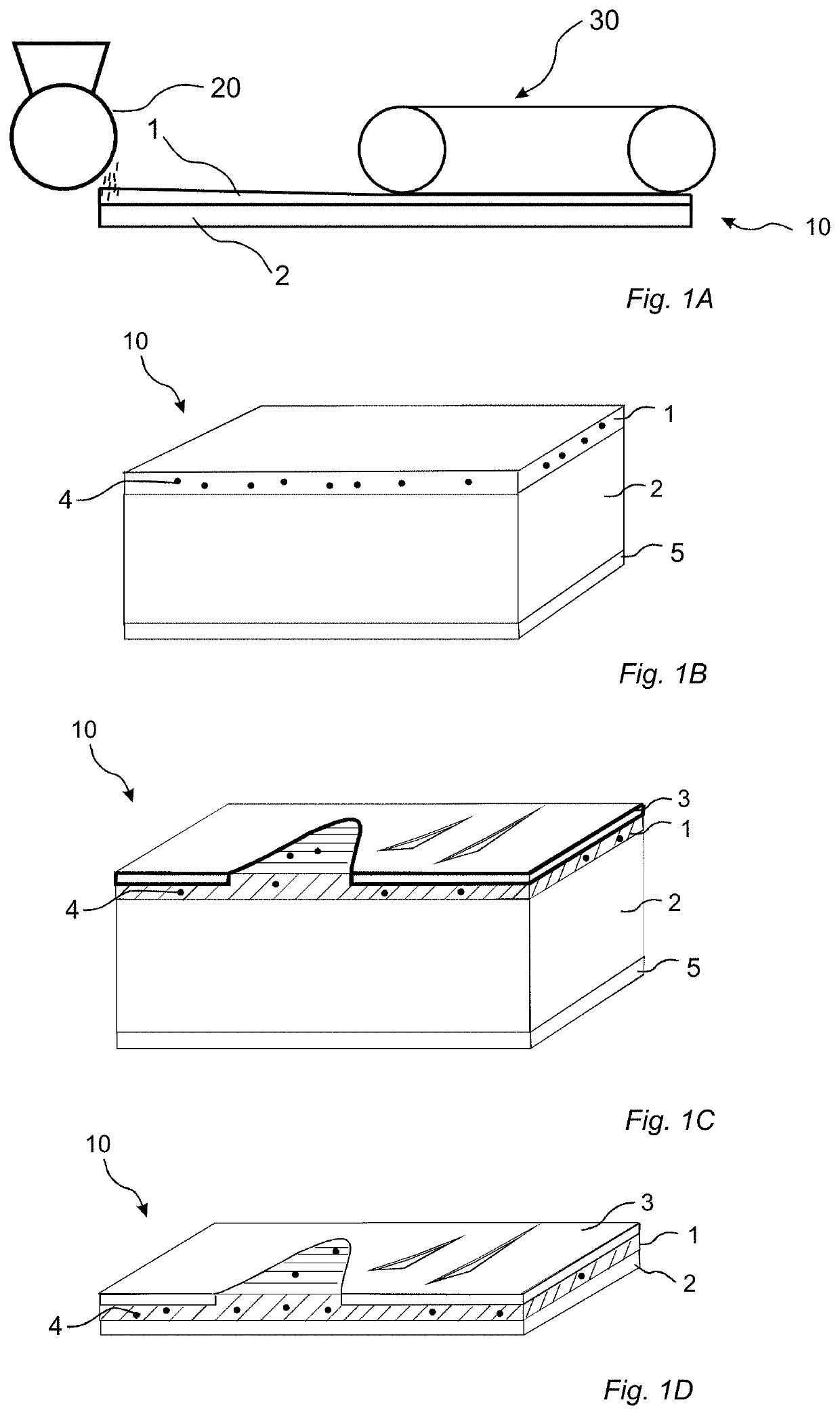
Method used
Image

Examples
example 1
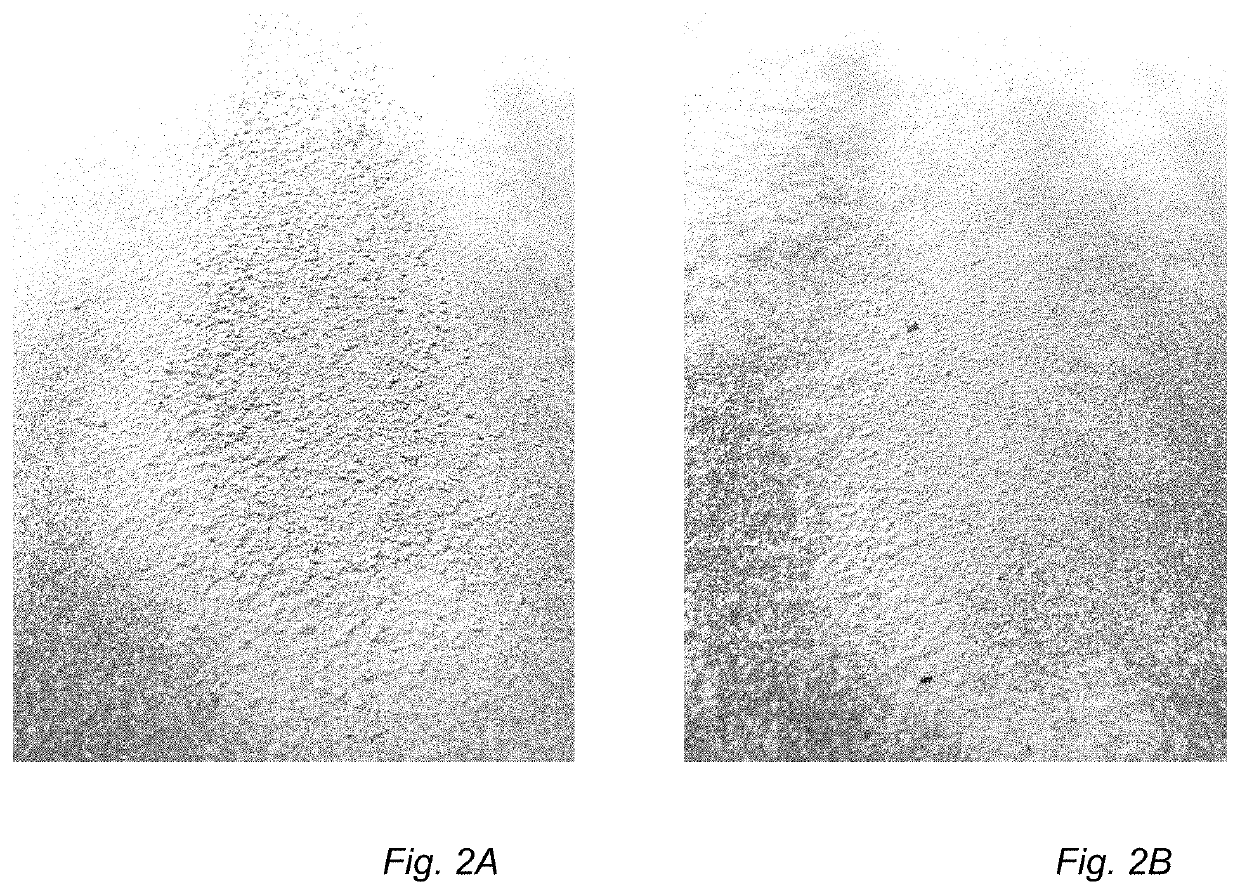
[0183]Different powder formulations comprising wood fibres and melamine-formaldehyde resin were made with increasing concentration of ASP® G90, a fine particle aluminium silicate, in order to investigate a connection between the powder free flow and the concentration of ASP® G90 as demonstrated in Table 1. The powder formulations were placed in glass jars to approximately half their volume and visually evaluated as the powders were let flowing by adding an external force to the jars. The typical powder which was considered was flowing without forming aggregates and did not show heavy dust formation which tended to partly adsorb to the jar walls. Acceptable formulation has a more even particle size distribution (FIG. 2B) compared to the reference powder (FIG. 2A).
TABLE 1Free flow experiment with different concentrations of ASP ® G90ASP G90MFWood fibresFormulation(wt %)(wt %)(wt %)A (Ref)05446B153.545.5C25345D352.544.5E551.542.5
[0184]Formulation B-E showed significantly higher free fl...
example 2
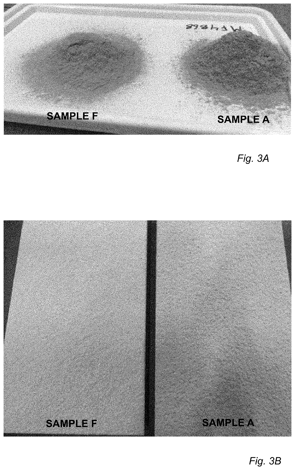
[0185]Different powder formulations comprising wood fibres and a melamine-formaldehyde resin were made with increasing concentration of AEROSIL® 200, a very fine particle fumed silica, in order to investigate a connection between the powder free flow and the concentration of AEROSIL 200®. The mixture compositions are shown in Table 2. The powder formulations were evaluated as described in the Example 1.
TABLE 2Free flow experiment with different concentrationsof AEROSIL ® 200.AEROSIL ® 200MFWood fibresFormulation(wt %)(wt %)(wt %)A (Ref)05446F0.153.9546.95G352.544.5
[0186]Formulation F and G showed visually remarkable higher free flow than the reference A (Ref), which is further visualized in FIGS. 3A-3B, wherein Sample F is shown as compared to the reference sample A.
[0187]When formulations B-E and F-G were used further in the method of manufacturing a building element the formulation was easy to distribute, did not form aggregates. The formulation provided for an even layer thereby ...
example 3
[0188]From four standardised formulations (A-D in Table 3 below), wherein only the additive part was switched between different inorganic non-pigment fine cohesive particles. These formulations were then run in a permeability program using a Freeman Technology FT4 Powder Rheometer where air is forced through a powder bed at different pressures. Pressure drop is directly negative proportional to permeability. A plot of Pressure drop vs. Applied normal stress was obtained where a high pressure drop is due to a low permeability, meaning higher cohesion in the powder. All powders were then visually inspected and the flowability compared using the glass jar method mentioned in Example 1.
TABLE 3Standardised formulations.Recipe typeA (wt %)B (wt %)C (wt %)D (wt %)ReferenceWood fibre37.537.54041.542MF resin4952.55252.553Aluminium55555oxideAdditive8.5531—Additives usedMIKHART ® C (CaCO3)BaSO4 BB30EXPOLYGLOSS ® 90 / ASP ® G90 (aluminium silicate)Micro talcCalcinated kaolinALGOFLON ® (polytetraf...
PUM
| Property | Measurement | Unit |
|---|---|---|
| Length | aaaaa | aaaaa |
| Fraction | aaaaa | aaaaa |
| Pressure | aaaaa | aaaaa |
Abstract
Description
Claims
Application Information
 - R&D
- Intellectual Property
- Life Sciences
- Materials
- Tech Scout
- Unparalleled Data Quality
- Higher Quality Content
- 60% Fewer Hallucinations
Browse by: Latest US Patents, China's latest patents, Technical Efficacy Thesaurus, Application Domain, Technology Topic, Popular Technical Reports.
© 2025 PatSnap. All rights reserved.Legal|Privacy policy|Modern Slavery Act Transparency Statement|Sitemap|About US| Contact US: help@patsnap.com