Eureka AIR delivers breakthrough ideas for toughest innovation challenges, trusted by R&D personnel around the world.

Insulating heat dissipation coating composition and insulating heat dissipation unit formed using the same

Pending Publication Date: 2020-05-14
AMOGREENTECH CO LTD
View PDF3 Cites 4 Cited by
  • Summary
  • Abstract
  • Description
  • Claims
  • Application Information

AI Technical Summary

Benefits of technology

The present invention provides an insulating heat dissipation coating composition that has excellent thermal conductivity and thermal emissivity, allowing for the formation of an insulating heat dissipation coating layer with excellent heat dissipation and insulation properties. The coating layer has strong adhesion to surfaces and durability against physical or chemical stimuli such as external heat, organic solvents, moisture, and shock. The heat dissipation filler dispersed in the coating exhibits excellent dispersibility, resulting in uniform insulation and heat dissipation performance. The coating has a smooth surface, excellent leveling properties, and surface quality, making it suitable for use in various industries.

Problems solved by technology

However, many types of fillers, which are in a heat dissipation coating layer, for enhancing heat dissipation performance also have conductivity, and in this case, they have difficulty in being used in applications requiring both heat dissipation and electrical insulation.
In addition, although an insulating heat dissipation coating layer has both an insulating property and a heat dissipation property, it is difficult to attain all physical properties of the formed insulating heat dissipation coating layer, for example, durability, heat dissipation performance and an adhesive strength to a surface to be coated, and there is a serious problem with the surface quality of the insulating heat dissipation coating layer, for example, an uneven or filler-protruding surface of the insulating heat dissipation coating layer.
Further, heat dissipation coating layers which have been known to have an excellent heat dissipation property have a problem of difficult thermal emission to the outside of the layers because they have excellent thermal conductivity in the layers, but have low thermal emissivity at an interface between the heat dissipation coating layer and an air layer.

Method used

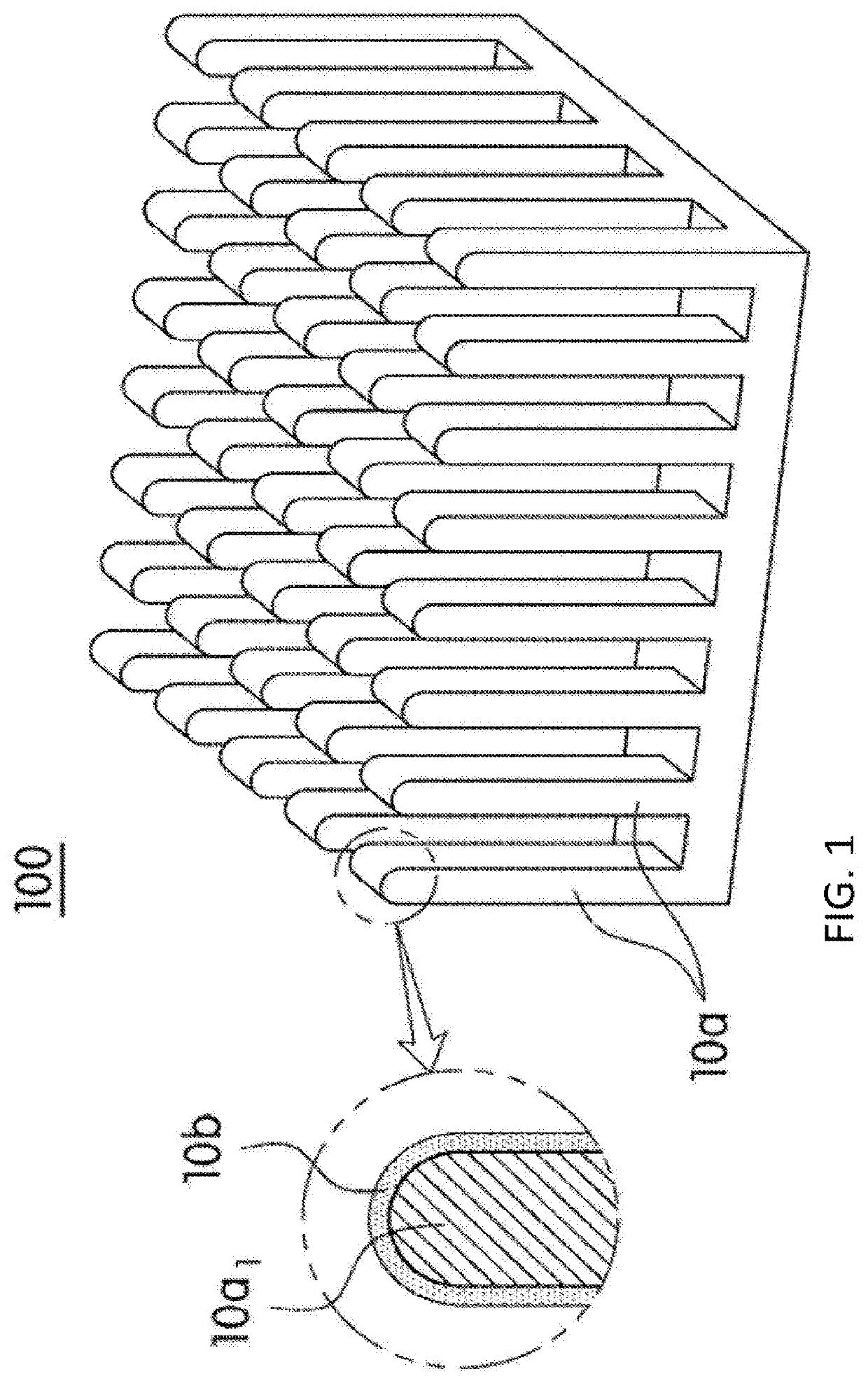
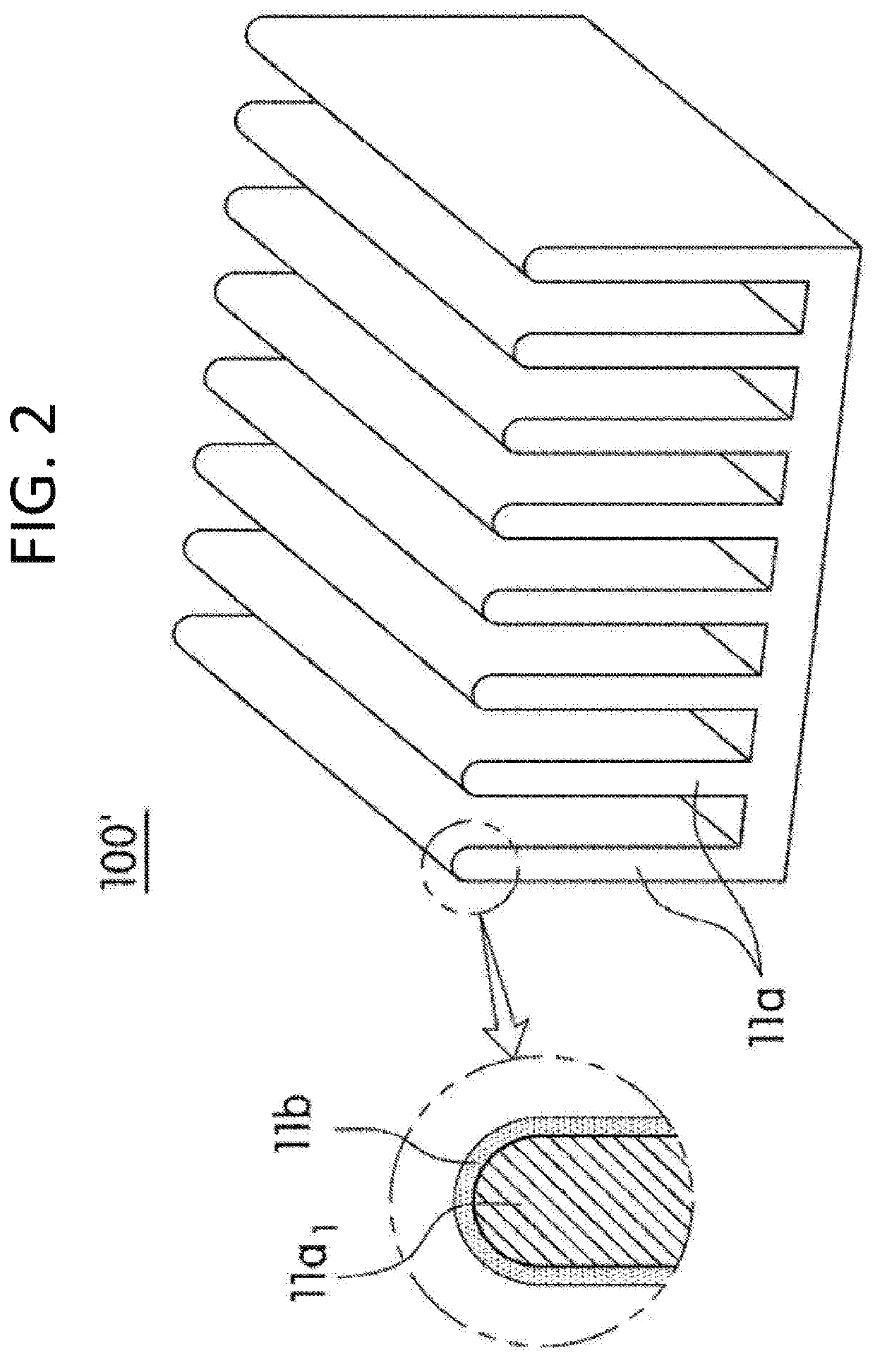
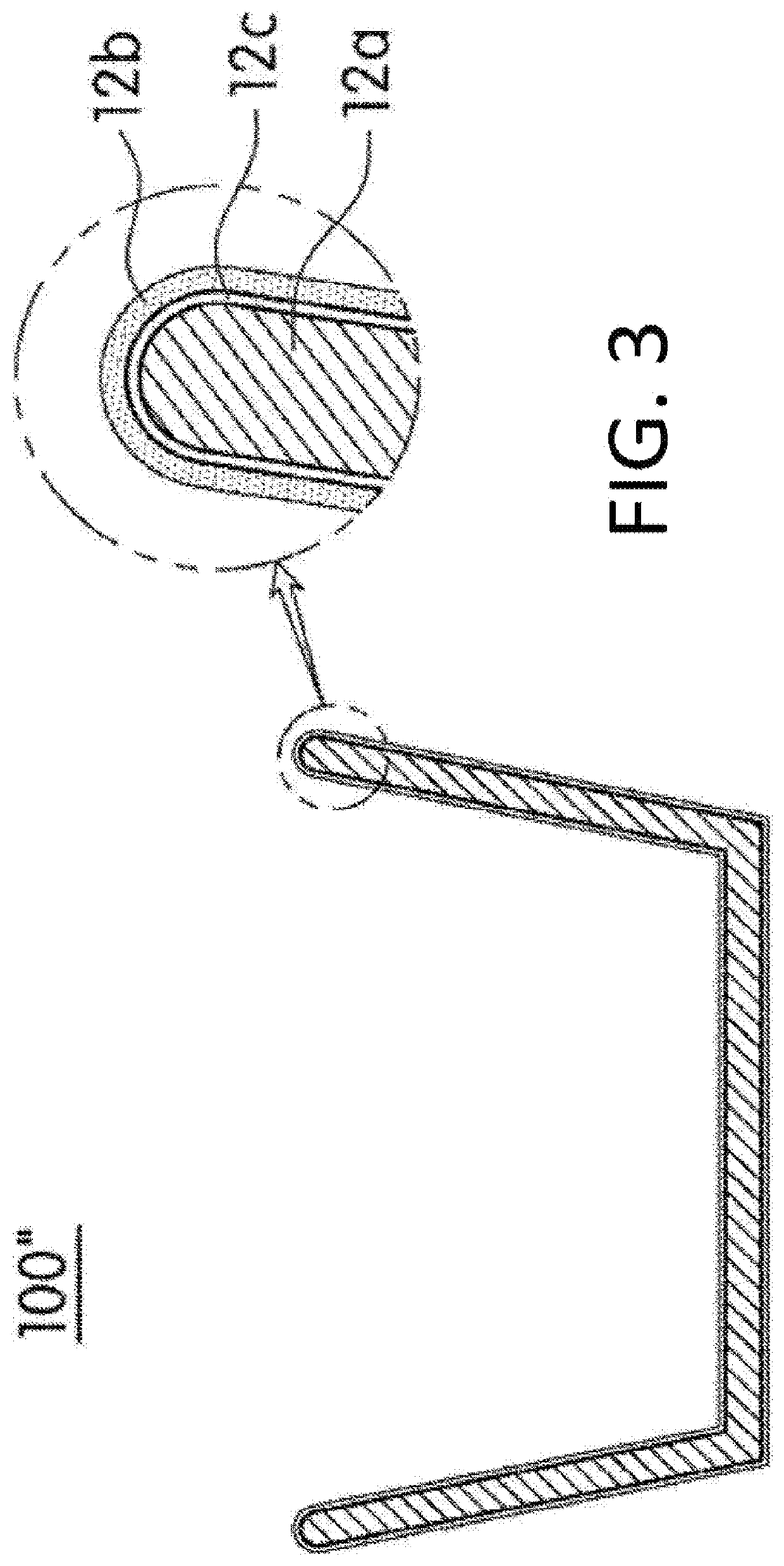

Image

  • Insulating heat dissipation coating composition and insulating heat dissipation unit formed using the same
  • Insulating heat dissipation coating composition and insulating heat dissipation unit formed using the same
  • Insulating heat dissipation coating composition and insulating heat dissipation unit formed using the same

Examples


example 1

[0116]A coating layer-forming component was prepared by mixing 60 parts by weight of a curing agent including a polyethylene polyamine as a first curing agent and 2,4,6-tris[N,N-dimethylamino]methyl]phenol as a second curing agent in a weight ratio of 1:1, 47 parts by weight of silicon carbide having an average particle diameter of 5 μm and a ratio of D50 to D97 of 1:1.6, 3 parts by weight of an epoxy-based silane compound as a physical property-enhancing component (Shanghai Tech Polymer Technology, Tech-7130), 44 parts by weight of talc as a colorant, 44 parts by weight of titanium dioxide as a quencher, 22 parts by weight of trizinc bis(orthophosphate) as a flame retardant, 0.5 part by weight of 2-(2′-hydroxy-3,5′-di(1,1-dimethylbenzyl-phenyl)-benzotriazole as an UV stabilizer, 1 part by weight of 2-hydroxyphenylbenzothiazole as an antioxidant, 5 parts by weight of a condensate of isobutylaldehyde and urea as a dispersant, and 13 parts by weight of 1-butanol, 13 parts by weight of...

examples 2 to 23

[0118]Insulating heat dissipation coating compositions shown in Tables 1, 2, 3 or 4 were prepared in the same manner as described in Example 1, except that an average particle diameter or particle size distribution of an insulating heat dissipation filler, a weight ratio of curing agents, or the molecular weight of a subject resin was changed as shown in Table 1, 2, 3 or 4.

experimental example 1

[0120]Each of the heat dissipation coating compositions prepared in the examples and the comparative examples was spray-coated onto the entire surface of a base which was formed of aluminum (Al 1050) and had a thickness of 1.5 mm and a size of 35 mm×34 mm (width×length) to the final thickness of 25 μm and thermally treated at 150° C. for 10 minutes, thereby manufacturing a heat dissipation unit on which an insulating heat dissipation coating layer was formed, and then physical properties as below were evaluated and shown in Tables 1 to 4.

[0121]1. Evaluation of thermal conductivity

[0122]A heat dissipation unit was placed in the middle of an acryl chamber having a size of 32 cm×30 cm×30 cm (width×length×height), and then a temperature in the chamber and a temperature of the heat dissipation unit were controlled to 25±0.2° C. Subsequently, a test specimen was prepared by adhering an LED having a size of 20 mm×20 mm (width×length) as a heat source to the heat dissipation unit using a th...


PUM

PropertyMeasurementUnit
Temperatureaaaaaaaaaa
Fractionaaaaaaaaaa

Abstract

An insulating heat dissipation coating composition including a coating layer-forming component including a subject resin, and an insulating heat dissipation filler. Therefore, the coating composition may have excellent thermal conductivity and excellent thermal emissivity, and therefore an insulating heat dissipation coating layer which exhibits excellent heat dissipation performance and has insulating property may be formed. In addition, the heat dissipation coating layer formed thereby has a very excellent adhesive strength to a surface to be coated so as to significantly prevent peeling of the coating layer during use, and to maintain durability of the coating layer even against a physical or chemical stimulus such as external heat, organic solvent, moisture or shock, which is generated after the coating layer is formed.

Description

CROSS REFERENCE TO RELATED APPLICATION[0001]This application is a 35 U.S.C. 371 National Phase Entry Application from PCT / KR2017 / 005427, filed May 24, 2017, which claims the benefit of Korean Patent Application No. 10-2016-0063683 filed on May 24, 2016, the disclosures of which are incorporated herein in their entirety by reference.TECHNICAL FIELD[0002]The present invention relates to an insulating heat dissipation coating composition, and more particularly, to an insulating heat dissipation coating composition which exhibits both a heat dissipation property and an insulating property and an insulating heat dissipation unit coated therewith.BACKGROUND ART[0003]Generally, a heat dissipation member is mounted on a heat-generating part to prevent malfunctions caused by heat generated in various parts included in a device during use of an electronic device. A heat dissipation member such as a heat dissipation plate or a heat sink is for rapidly emitting heat in a device or part to the o...

Claims


Application Information

Patent Timeline
IPC IPC(8): H05K7/20C09D163/00C08K3/14C08K5/17
CPCC08K3/14H05K7/20427C08K5/17C09D163/00C09D5/00C09D201/00C09D7/40C08K3/013C08K5/0041C08K2201/003C08G2650/56C08G59/502C08G59/56C09D7/61C09D7/63C08G59/42C08G59/245C08K3/34C08G59/58
Inventor KIM, MOON HOEHWANG, SEUNG JAEHWANG, MOON YOUNG
Owner AMOGREENTECH CO LTD
Why Eureka
Eureka Blog
Learn More