
Environmentally friendly aluminum coatings as sacrificial coatings for high strength steel alloys

a technology of aluminum coating and high strength steel alloy, which is applied in the direction of chromatisation, electrodes, etc., can solve the problems of not being able to coat internal and deeply recessed surfaces, handling hazardous and non-environmental plating solutions, and not being able to meet the requirements of environmental protection. , to achieve the effect of facilitating handling

Pending Publication Date: 2020-04-23
THE BOEING CO
View PDF12 Cites 3 Cited by
  • Summary
  • Abstract
  • Description
  • Claims
  • Application Information

AI Technical Summary

Benefits of technology

The patent application is about a safer and more environmentally friendly process for coating ferrous alloy steel with aluminum. The process meets health and safety regulations and is suitable for use in various applications such as aeronautical, automotive, marine, construction, industrial, and household applications. This aluminum coating can replace Ni-free Cd for high strength steel alloys.

Problems solved by technology

Numerous alternative technologies are being developed and tested to replace cadmium sacrificial coatings for high strength alloy steels and some of them are promising for some applications, but none of them is yet authorized for all applications.
Therefore, it involves handling hazardous and non-environmentally friendly plating solutions.
Some of the disadvantages of this technology include the limited ability to coat internal and deeply recessed surfaces: depending on the orientation of the part's surfaces in the chamber, the coating thickness may not be equivalent in all areas (especially for internal diameters), the coating does not pass the re-embrittlement test as per HSSJTP [High-Strength Steel Joint Test Protocol, for Validation of Alternatives to Low Hydrogen Embrittlement Cadmium For High-Strength Steel Landing Gear and Component Applications, Jul. 31, 2003; AFRL / MLSC / WPAFB, OH 45433-7718; Approved for public release; distribution unlimited (26 March 2003)] and large components may be physically restricted from IVD-Al coating by the dimensions of the vacuum vessel.
However, some of the drawbacks of this technology are the high cost and the fact that so far only limited applications are authorized.
However, because of the rather negative standard potential of aluminum, it is not possible to electroplate aluminum from aqueous solutions because hydrogen evolution occurs at the potentials at which aluminum is plated, making the process not efficient and causing hydrogen embrittlement to the substrate, which is not acceptable for the high strength alloys used in aeronautical applications.
A key disadvantage of this process is that it is not environmentally friendly, since it employs a toluene-based toxic and very flammable solution which also contains pyrophoric alkylaluminum constituent components.
However, the process still involves handling toxic and non-environmentally friendly plating solutions [US2007261966A1, 2007-11-15, Alumiplate Inc.
However, no data was found regarding the throwing power and the hydrogen embrittlement of this formulation, key requirements in order to use the coating as an alternative to Cd sacrificial coatings for high strength steel alloys.
In addition, this process contains aromatic organic solvents so it still implies environmental, handling, and health issues.
However, in spite of the elimination of organic solvents, this formulation still has some handling and health risks since the hydrides in this bath liberate flammable gases in contact with water, which may cause burns.
Also, in this particular case, no hydrogen embrittlement performance has yet been reported.
In conclusion, despite the potential and promising results achieved in aluminum electroplating with these novel electrolytes, it seems that all the ionic liquid based formulations developed so far that can provide a balanced compromise between the basic properties required for Cd replacement still require non-environmentally friendly, toxic and / or hazardous additives and solvents.

Method used


Image

  • Environmentally friendly aluminum coatings as sacrificial coatings for high strength steel alloys
  • Environmentally friendly aluminum coatings as sacrificial coatings for high strength steel alloys
  • Environmentally friendly aluminum coatings as sacrificial coatings for high strength steel alloys

Examples


examples

1. Ionic Liquid Electrolytes

[0137]The ionic liquid electrolytes used in these examples were synthesized as follows:

[0138]B01: Either the as-received Basionics™ Al01 ionic liquid electrolyte from BASF or the house-made AlCl3-EMIC 60:40 electrolyte (see below) were independently used as baseline electrolytes to be modified with the different additives.

[0139]AlCl3-EMIC 60:40 electrolyte was prepared by mixing the corresponding amounts of aluminum trichloride and 1-ethyl-3-methyl-imidazolium chloride, as follows: The 1-ethyl-3-methylimidazolium chloride [EMIC] (Fluka Ref. 30764, purity min 93%), was dried at 70° C. under vacuum for several hours. Then, it was placed into a glass vessel. The aluminum trichloride [AlCl3] (Across Organics Ref. 19578, anhydrous, 99%, granules) was weighted (as received) inside a glovebox filled with argon inside a glass dispenser; then, it was transferred to an addition funnel, taken out of the glovebox, and placed on top of the glass vessel already contain...


PUM

PropertyMeasurementUnit
temperatureaaaaaaaaaa
current densityaaaaaaaaaa
temperatureaaaaaaaaaa

Abstract

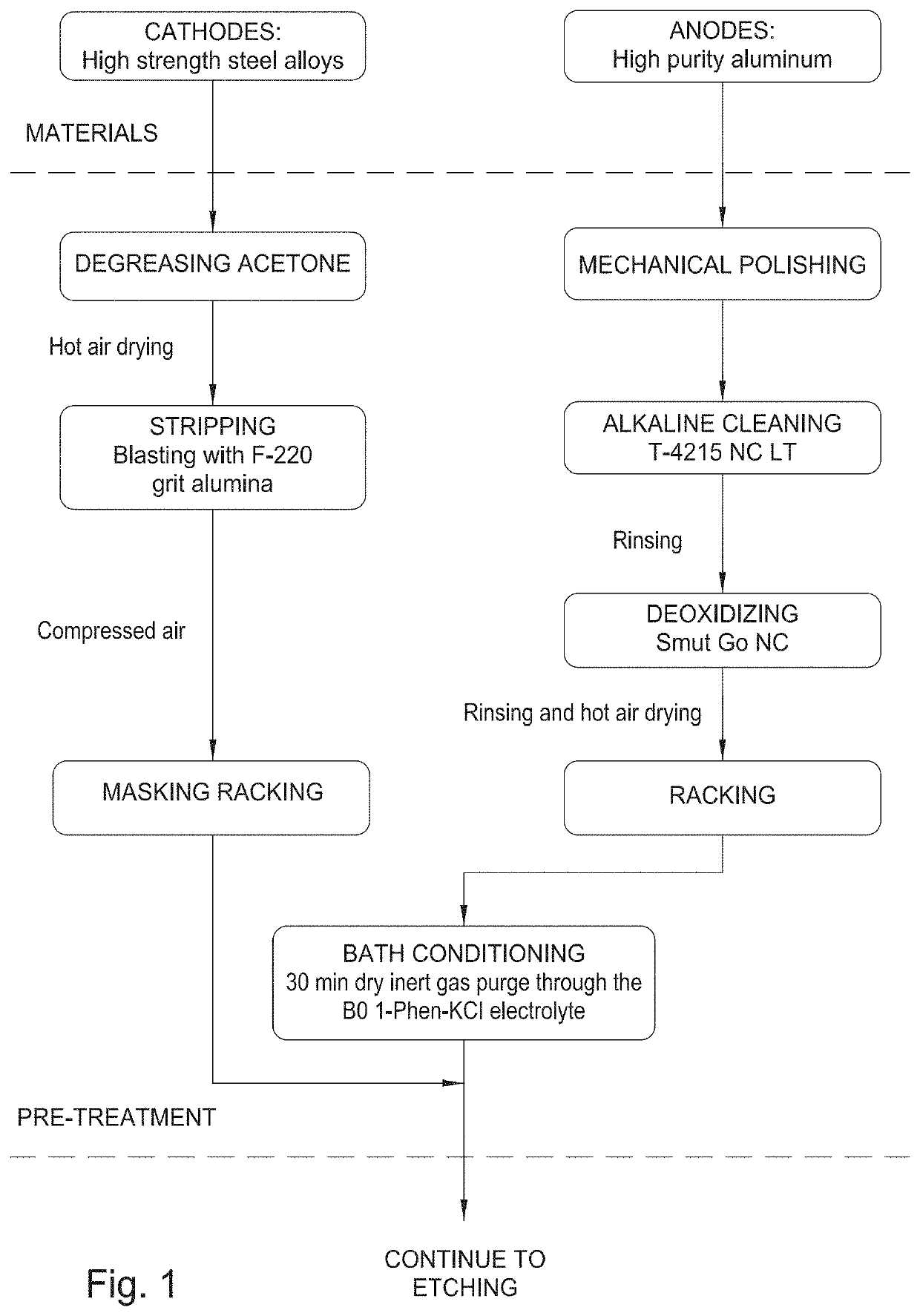
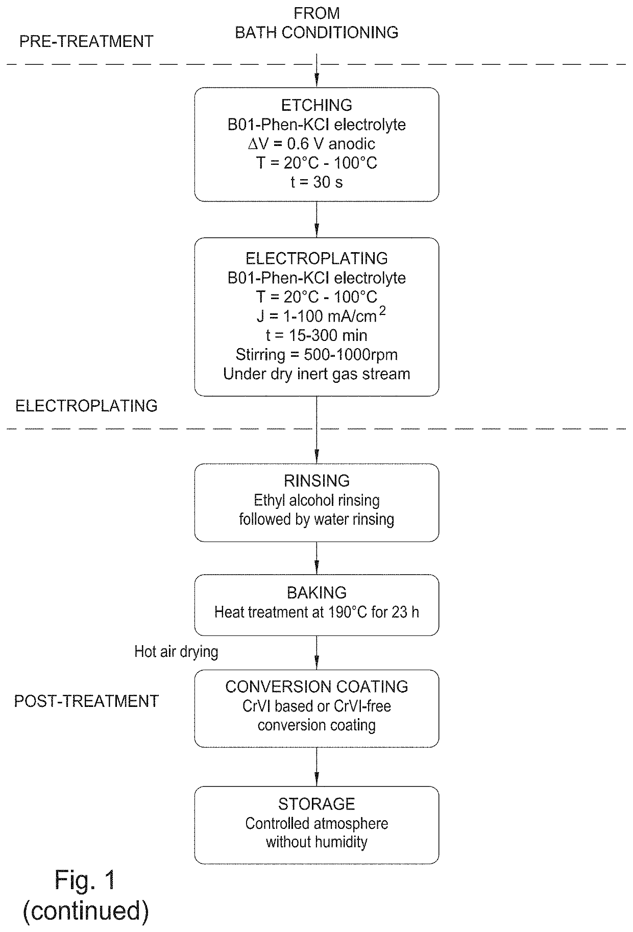
Electroplating process is described for coating a ferrous alloy steel cathode substrate with an aluminum coating, the process comprises: a) immersing an aluminum anode substrate in a plating bath formulation comprising: a source of aluminum, an ionic liquid, a brightening agent, and a metal-salt compound; b) etching the cathode substrate by immersing it into the aluminum plating bath and conducting an anodic polarization step; c) electroplating the etched cathode substrate with the aluminum plating bath formulation; and d) rinsing with alcohol and water, and drying. Preferably, the process further comprises a heat treatment applied to the aluminum coated ferrous steel alloy obtained in step d).

Description

CROSS-REFERENCE TO RELATED APPLICATIONS[0001]This application claims benefit of European Application Serial Number EP 15382212.7, filed Apr. 28, 2015 and is a continuation application of U.S. application Ser. No. 15 / 137,965 filed on Apr. 25, 2016, which are both hereby incorporated by reference in their entirety.FIELD OF DISCLOSURE[0002]This specification refers to an environmentally friendly electroplating process for coating a ferrous alloy steel substrate, preferably a high strength steel alloy, using a novel aluminum bath formulation comprising more safe-handling, less-hazardous and environmentally friendly components than the formulation used in the AlumiPlate™ process, which was the most promising aluminum coating alternative for Cd replacement known until now. Additionally, the present patent application refers to both the aluminum coating and the coated ferrous alloy steel substrate obtained by such process, as well as the use of both in applications such as aeronautical, au...

Claims


Application Information

Patent Timeline
Patent Type & Authority Applications(United States)
IPC IPC(8): C25D3/44C25D7/00C25D5/52C25D5/00C25D5/36C25D17/10C25D3/66C25D5/50C25D11/38
CPCC25D3/44C25D17/10C25D5/50C25D11/38C25D5/52C25D5/36C25D7/00C25D3/665C25D5/003
Inventor IZAGIRRE ETXEBERRIA, USOASANCHEZ CUPIDO, LAURALAPEÑA REY, NIEVESUNZURRUNZAGA, AINHOA
Owner THE BOEING CO
Learn More