Solid electrolytic capacitor
- Summary
- Abstract
- Description
- Claims
- Application Information
AI Technical Summary
Benefits of technology
Problems solved by technology
Method used
Image


Examples
first embodiment
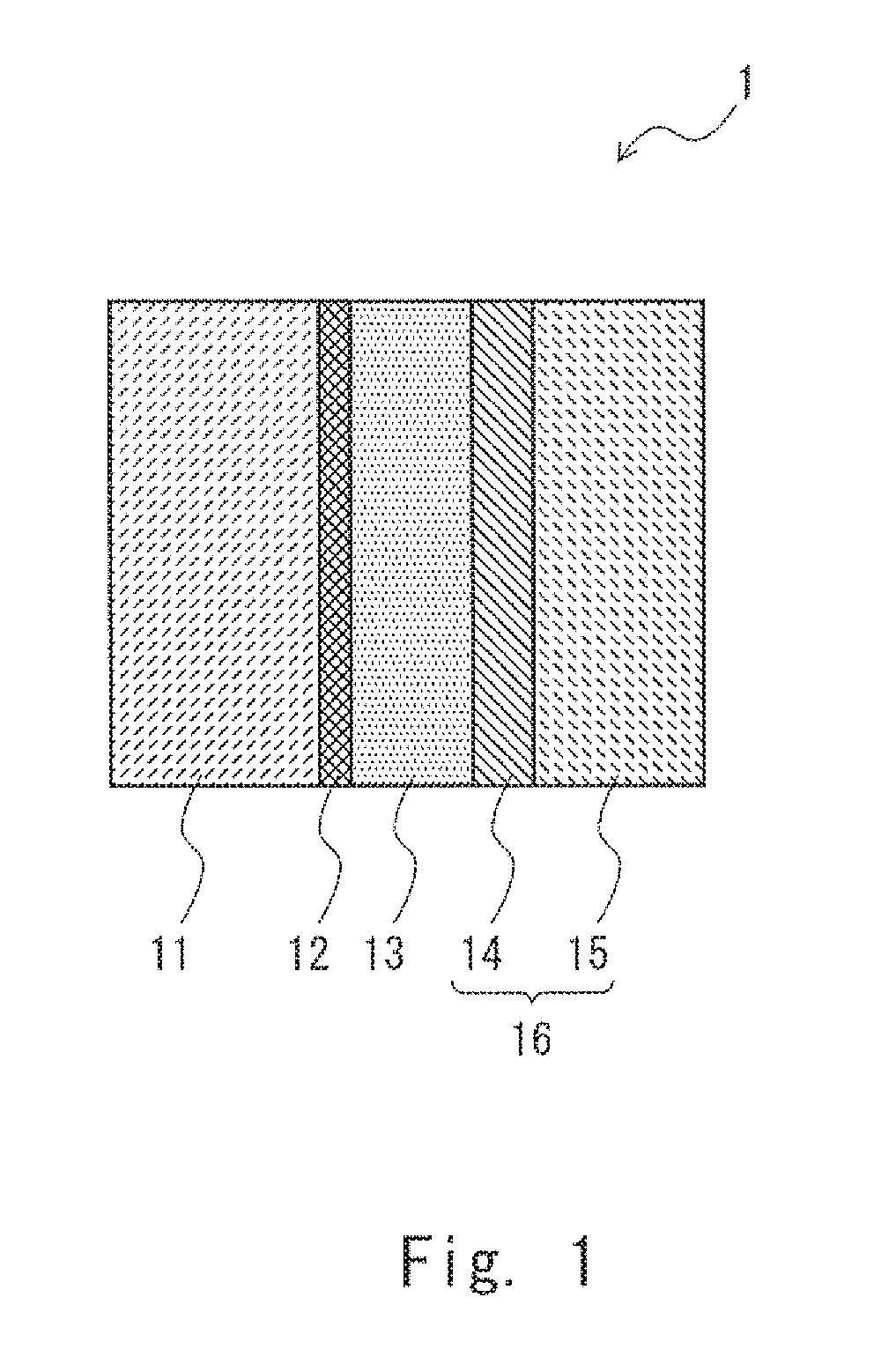
[0017]Hereinafter, with reference to the drawings, embodiments of the present invention will be described. FIG. 1 is a cross-sectional view showing a solid electrolytic capacitor according to a first embodiment. As shown in FIG. 1, a solid electrolytic capacitor 1 according to this embodiment includes an anode body 11, a dielectric layer 12 that is arranged on a surface of the anode body 11, a solid electrolyte layer 13 formed on a surface of the dielectric layer 12, and a cathode body 16. The cathode body 16 includes a graphite layer 14 and a silver layer 15 and functions as a cathode extraction layer that connects the solid electrolyte layer 13 and a cathode (not shown).
[0018]The anode body 11 is formed using valve metal. The valve metal may be, for example, aluminum, tantalum, niobium, titanium, zirconium, hafnium, tungsten, and alloys including the same. These materials of the valve metal are merely examples and any material may be used in the solid electrolytic capacitor accord...
second embodiment
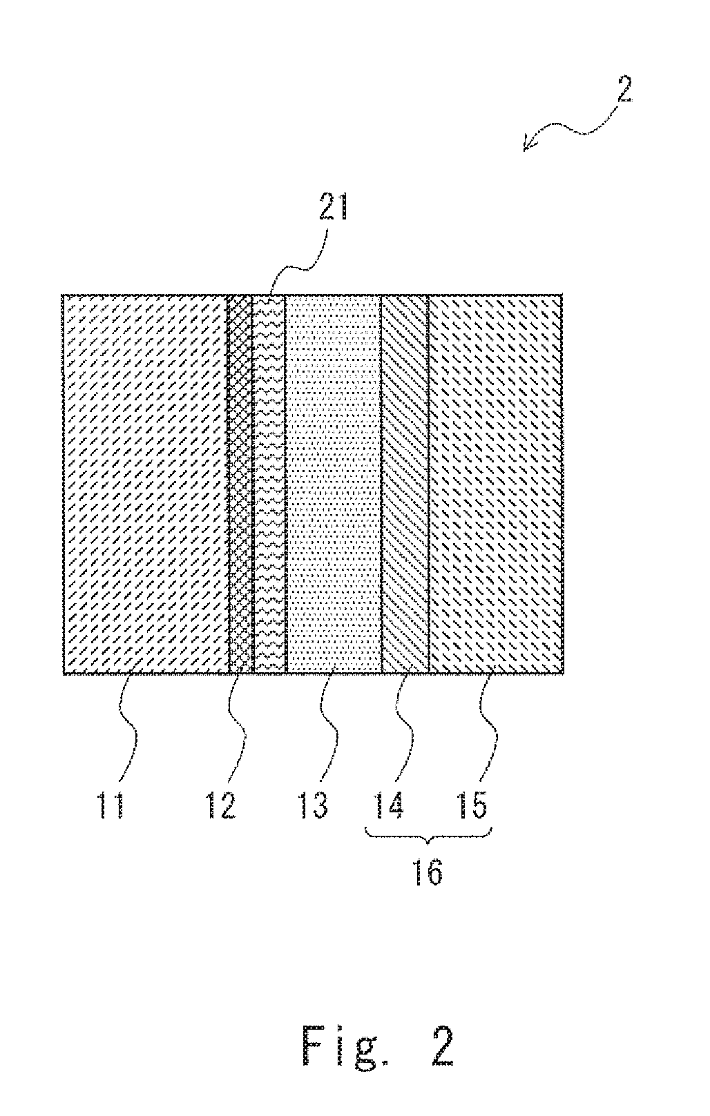
[0039]Next, a second embodiment of the present invention will be described. FIG. 2 is a cross-sectional view showing a solid electrolytic capacitor according to the second embodiment. A solid electrolytic capacitor 2 according to this embodiment is different from the solid electrolytic capacitor 1 described in the first embodiment in that a diffusion suppressing layer 21 is formed between the dielectric layer 12 and the solid electrolyte layer 13. Since the other components of the solid electrolytic capacitor 2 according to the second embodiment are similar to / the same as those of the solid electrolytic capacitor 1 according to the first embodiment, such similar / the same components are denoted by the same reference symbols and overlapping descriptions will be omitted.
[0040]As shown in FIG. 2, the solid electrolytic capacitor 2 according to this embodiment includes the diffusion suppressing layer 21 that is formed between the dielectric layer 12 and the solid electrolyte layer 13. Th...
example 1
[0047]A tantalum plate, which is valve metal, was used for the anode body of the solid electrolytic capacitor. Then the tantalum plate was electrolytic-oxidized in a phosphoric acid aqueous solution with an applied voltage of 100 V to form the dielectric layer (oxide film layer) having a thickness of about 170 nm on the whole surface of the tantalum plate. After that, the solid electrolyte layer formed of the conductive zinc oxide film having a thickness of about 1 μm was formed on a surface of the dielectric layer using the sputtering method. The area of the solid electrolyte layer that was formed was 70 cm2. Then the graphite layer (about 1 μm) and the silver paste layer (about 10 μm) were formed on the solid electrolyte layer to obtain the solid electrolytic capacitor according to Example 1.
[0048]The capacity of the solid electrolytic capacitor that was produced was measured using an LCR meter. The value of the capacity at 120 Hz and that at 100 kHz were evaluated. Further, the s...
PUM
| Property | Measurement | Unit |
|---|---|---|
| Electrical conductivity | aaaaa | aaaaa |
| Electrical conductivity | aaaaa | aaaaa |
| Electrical conductivity | aaaaa | aaaaa |
Abstract
Description
Claims
Application Information
 - R&D
- Intellectual Property
- Life Sciences
- Materials
- Tech Scout
- Unparalleled Data Quality
- Higher Quality Content
- 60% Fewer Hallucinations
Browse by: Latest US Patents, China's latest patents, Technical Efficacy Thesaurus, Application Domain, Technology Topic, Popular Technical Reports.
© 2025 PatSnap. All rights reserved.Legal|Privacy policy|Modern Slavery Act Transparency Statement|Sitemap|About US| Contact US: help@patsnap.com