
Bipolar plate structure for fuel cell

a fuel cell and bipolar plate technology, applied in the direction of fuel cells, solid electrolyte fuel cells, collectors/separators, etc., can solve the problems of difficult to expect uniform power generation in the entire reaction region, design restrictions, and difficulty in manufacturing metallic bipolar plates, so as to improve water discharge capability, improve the performance and efficiency of the fuel cell, and increase the limiting current density and power density

Active Publication Date: 2016-11-24
HYUNDAI MOTOR CO LTD
View PDF0 Cites 2 Cited by
  • Summary
  • Abstract
  • Description
  • Claims
  • Application Information

AI Technical Summary

Benefits of technology

The patent text describes a new structure for a bipolar plate in a fuel cell that can produce power more evenly across the entire reaction region, increasing the current density and power density while improving performance and efficiency. Additionally, the new structure improves the fuel cell's water discharge capability and increases contact with the coolant, improving thermal efficiency.

Problems solved by technology

However, it is difficult for the metallic bipolar plate manufactured by press working to realize a complex shape.
The bipolar plate manufactured by processing a metal material using a press causes design restrictions due to the shape of the bipolar plate itself.
For this reason, it is difficult to expect uniform power generation in the entire reaction region due to a difference in the electrochemical reaction.
For this reason, the bipolar plate has a disadvantage in that the substances are transferred to the catalyst layer depending on only diffusion by a concentration difference and a partial pressure difference between the channels 11a and 11b and the MEA 21.
Therefore, it is difficult to transfer the substances to the catalyst layer by the flow in the bipolar plate.
Therefore, the limiting current density of the fuel cell decreases, and thus, the performance of the fuel cell may deteriorate.
In addition, the performance of the fuel cell may not be improved in a high power section, and it is difficult to discharge water as a by-product produced by the electrochemical reaction since it is difficult to remove water present in the GDL.
Moreover, since the reactant gas concentration required for the electrochemical reaction is not transferred to the catalyst layer in the rear end portion (the outlet portion) of the flow field channel, a power loss may result.

Method used


Image

  • Bipolar plate structure for fuel cell
  • Bipolar plate structure for fuel cell
  • Bipolar plate structure for fuel cell

Examples


Embodiment Construction

[0061]Hereinafter, reference will now be made in detail to various embodiments of the present inventive concept, examples of which are illustrated in the accompanying drawings and described below. While the invention will be described in conjunction with exemplary embodiments, it will be understood that present description is not intended to limit the invention to those exemplary embodiments. On the contrary, the invention is intended to cover not only the exemplary embodiments, but also various alternatives, modifications, equivalents, and other embodiments, which may be included within the spirit and scope of the invention as defined by the appended claims.

[0062]As describe above, since the conventional bipolar plate for a fuel cell transfers the substances to the catalyst layer using only the diffusion of the reactant gases, it is difficult to achieve the uniform power generation in the entire reaction region due to the nonuniform gas concentration between the flow field section ...


PUM


Abstract

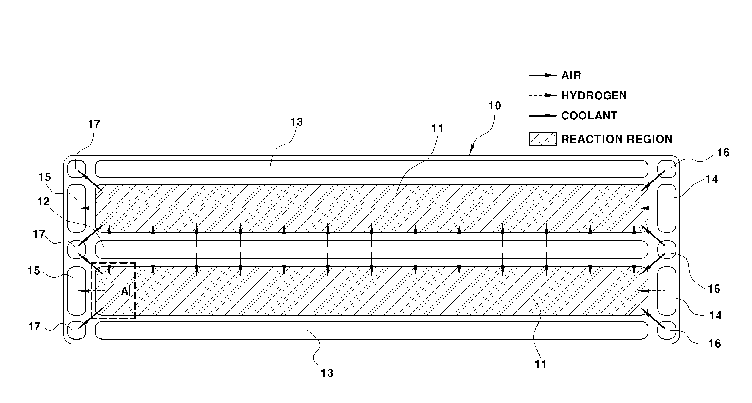
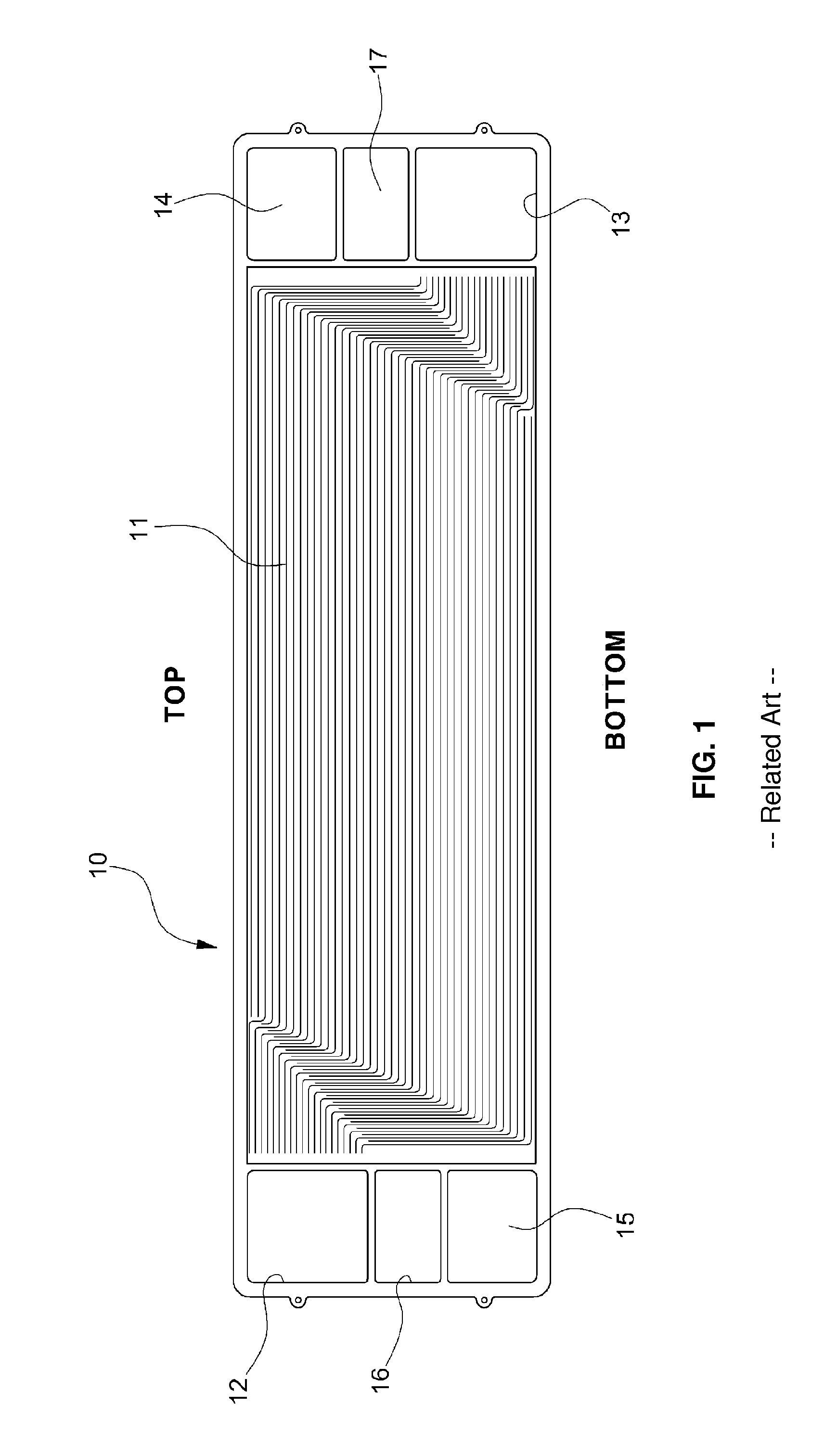
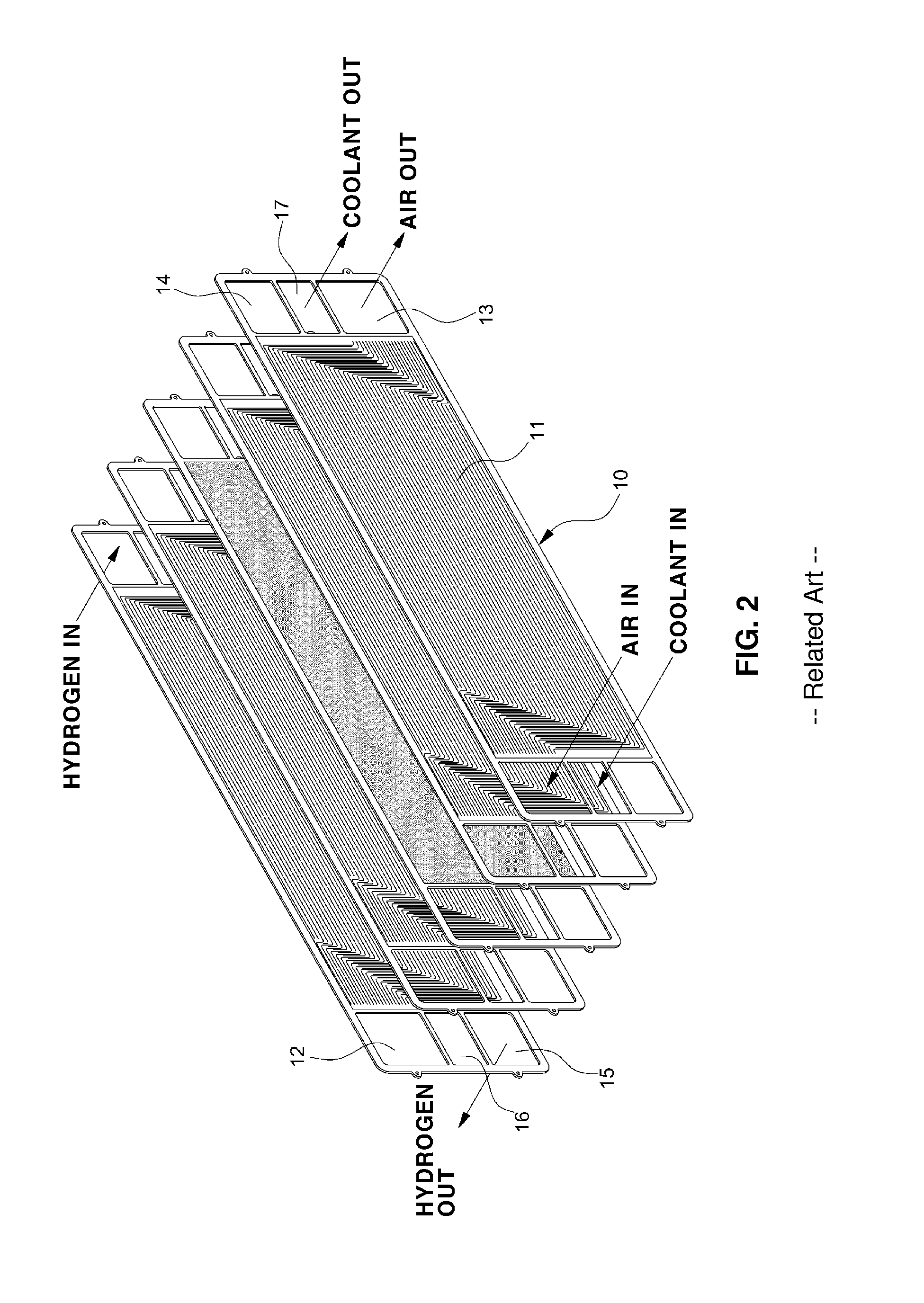
A bipolar plate structure for a fuel cell includes a cathode bipolar plate having a first flow field section to form cathode channels between the first flow field section and a first gas diffusion layer and a first land section to form coolant channels. An anode bipolar plate has a second flow field section to form anode channels between the second flow field section and a second gas diffusion layer and a second land section to form coolant channels. The cathode channels have an interdigitated channel structure, and the anode channels have a parallel channel structure. An air inlet manifold hole is formed along one of two long-side edge portions of a reaction region in the cathode and anode bipolar plates. An air outlet manifold hole is formed along the other of the two long-side edge portions of the reaction region.

Description

CROSS-REFERENCE TO RELATED APPLICATION[0001]This application claims under 35 U.S.C. §119(a) the benefit of priority to Korean Patent Application No. 10-2015-0070263 filed on May 20, 2015, the entire content of which is incorporated herein by reference.TECHNICAL FIELD[0002]The present disclosure relates to a bipolar plate structure for a fuel cell. More particularly, the present disclosure relates to a bipolar plate structure for a fuel cell, capable of achieving uniform power generation in an entire reaction region, increasing a limiting current density and a power density, and improving performance and efficiency of the fuel cell.BACKGROUND[0003]A polymer electrolyte membrane fuel cell (PEMFC) generates electricity by electrochemical reaction between hydrogen as fuel gas and oxygen (or air) as oxidant gas, which are reactant gases.[0004]The PEMFC has high efficiency, high current density, high power density, short start-up time, and rapid response to a load change, compared to othe...

Claims


Application Information

Patent Timeline
IPC IPC(8): H01M8/02
CPCH01M8/026H01M8/02H01M8/0202H01M8/0258H01M8/10H01M8/0267Y02E60/50
Inventor JEONG, HEE SEOK
Owner HYUNDAI MOTOR CO LTD
Learn More