
Novel powder

a metal powder and powder technology, applied in metal-working apparatus, arc welding apparatus, metallic material coating process, etc., can solve the problems of glass sticking/adhesion to the die surface, irregular formation of irregularities, oxidation of the die, etc., to reduce the impact on the environment, reduce the cost of materials, and reduce the effect of pores

Inactive Publication Date: 2016-05-19
HOGANAS AB
View PDF2 Cites 20 Cited by
  • Summary
  • Abstract
  • Description
  • Claims
  • Application Information

AI Technical Summary

Benefits of technology

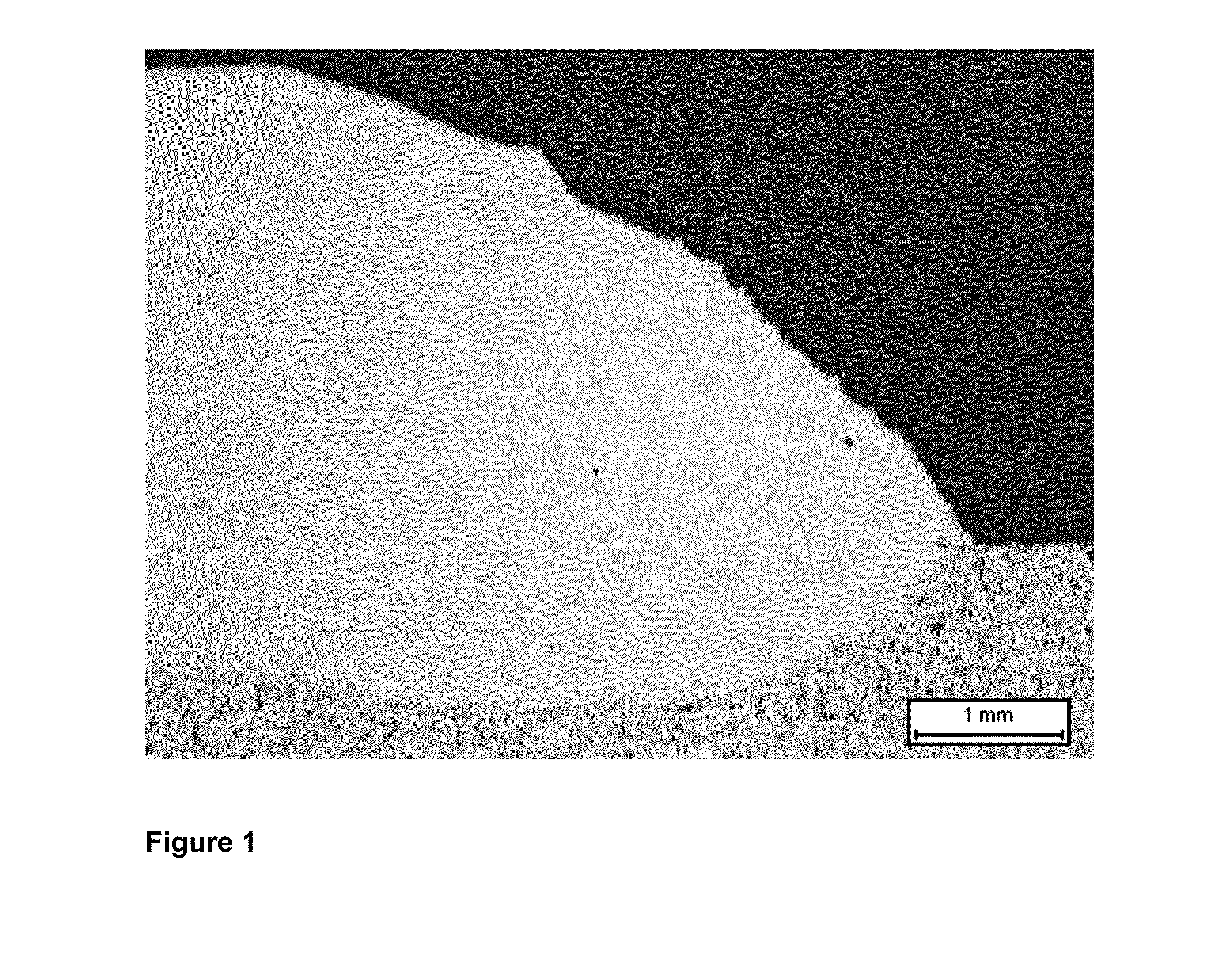
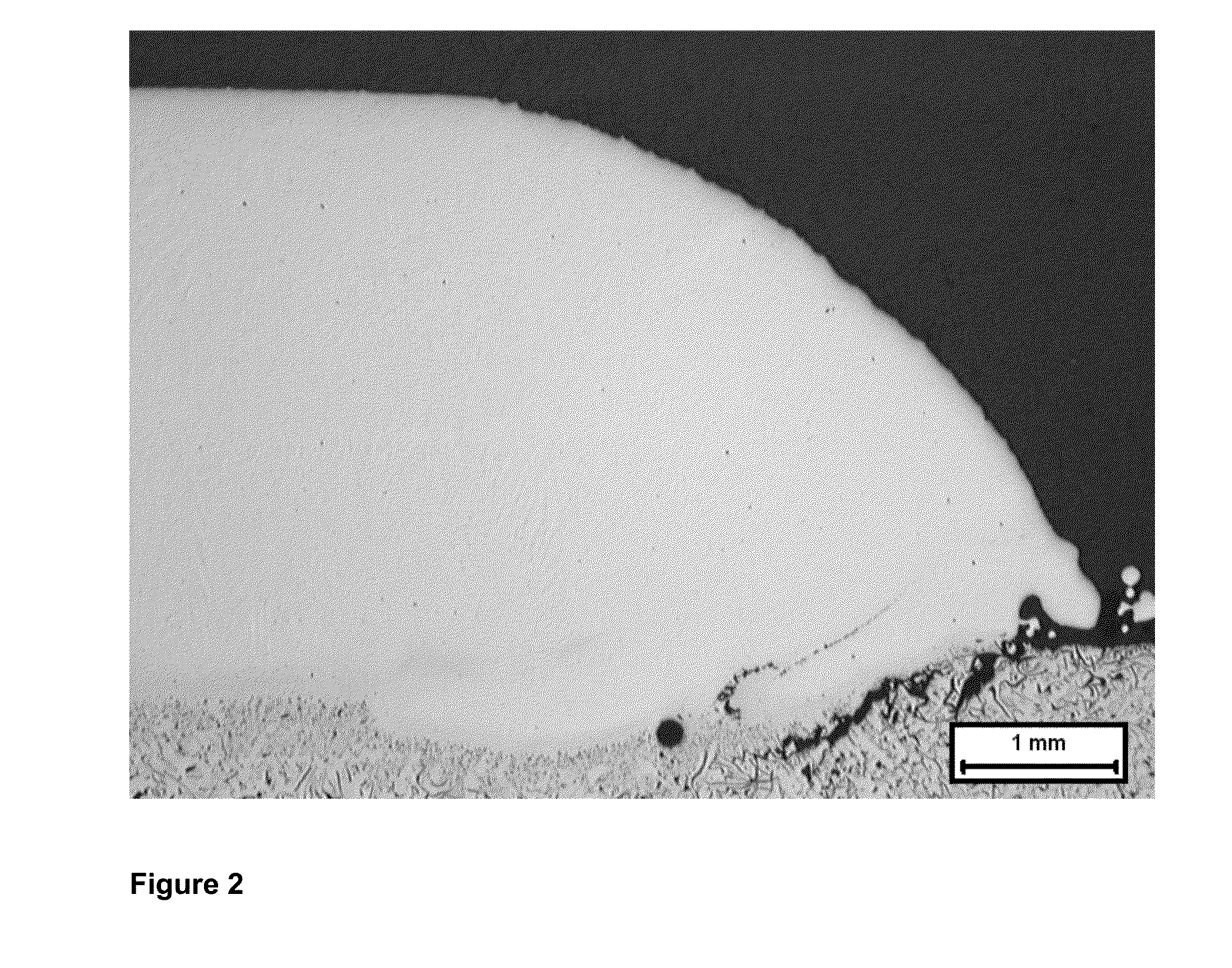
The present invention has shown that it is possible to increase the iron content of metal powder and use it for overlay welding without causing cracks. By using an alloy powder with a specific amount of iron, chromium, and nickel, the coating has similar properties to nickel based self fluxing grades, but with fewer cracks, less pores and graphite, lower material costs, and less harmful working conditions. The amount of chromium and nickel can be optimized to minimize crack formation in the cast iron heat affected zone. Additionally, the invention minimizes the use of nickel, reducing potential health and environmental impact during powder production, handling, and welding.

Problems solved by technology

This leads to three critical problems: sticking / adhesion of glass to the die surface and formation of irregularities (surface roughening); oxidation of the die, and; wear / pitting of the die.
These problems result in imperfections in the glass products and limit the service life of the die.
Hardfacing by overlay welding of lamellar cast iron is difficult as cast iron is sensitive to cracking due to the low strength of the graphite lamellas, low ductility and thermal expansion coefficient close to zero.
Due to cost and environmental and health concerns, it has long been a wish to reduce the alloying cost by introducing more Fe into the powders, but attempts to do so have not been successful, resulting in increased crack formation in the lamellar cast iron heat affected zone (HAZ).

Method used


Image

  • Novel powder
  • Novel powder
  • Novel powder

Examples


example 1

[0035]The powders used in the following examples were made by conventional gas atomization and were then sieved between 53-150 μm. The content of the various powders is shown in Table 1.

Crackpreven-SampleCBSiCrAlOtherNiFeHV30tionComparative0.21.02.961863323++example 1Comparative0.31.33.67853340++example 2Comparative00.91.6151865259−example 3A0.70.82.4201759316−B0.01.42.4191662353−C0.80.82.4101670319−D0.01.42.361674283+F0.01.52.573554347++G0.01.52.5123549331−H0.01.52.5203541330−I0.01.52.875039326++K0.21.42.575039356++L0.51.52.475039388++M0.01.52.6125133353++N0.01.52.8195027353++O0.01.53.26P =4938382++2%P0.01.42.66Mn =3540326++15%R0.11.62.576920347++S0.00.42.875040232++T0.01.63.675038373++U0.02.32.575038414++Note:All amounts in wt %.“++” denotes total crack length shorter than 500 μm; “+” denotes cracks between 500 and 1000 μm; and “−” denotes cracks longer than 1000 μm.

example 2

[0036]Lamellar cast iron pucks with 90 mm diameter and approx. 35 mm in height were coated as follows. The pucks were pre-heated in a furnace in air at 380° C. One layer with width of approximately 1 cm was deposited along the puck diameter. The following welding parameters were used: welding current 90-105 A, welding speed 6-7 cm / min, feeding rate 28-30 g / min, feed gas of 3.5 l / min, oscillation of the PTA beam, pilot current of 1-2 A. After welding the samples were cooled in vermiculite.

example 3

[0037]Lamellar cast iron pucks with 90 mm diameter and approx. 35 mm in height were laser cladded as follows. The pucks were pre-heated in a furnace in air at 380° C. One layer with width of approximately 1 cm was deposited along the puck diameter by using a 4 kW direct diode laser with a spot of 12×2 mm, equipped with a co-axial powder feeder. The following laser cladding parameters were used: 2 kW power, cladding speed between 4-5 mm / sec, powder feed rate 31 g / min and shield gas 10-11 l / min. The results achieved are shown in table 2.

TABLE 2SampleCBSiCrNiFeCrack preventionV0.01.52.875039++


PUM

PropertyMeasurementUnit
temperatureaaaaaaaaaa
surface temperatureaaaaaaaaaa

Abstract

The present invention concerns a new metal powder which is useful for coating cast iron parts. The invention also relates to a method for coating cast iron parts by using the new metal powder. Of special importance is the possibility to use the metal powder for coating the surfaces of glass moulds. The invention also relates to metal parts, such as cast iron parts, or glass moulds which are coated by the metal powder.

Description

FIELD OF THE INVENTION[0001]The present invention concerns a new metal powder which is useful for coating cast iron parts. The invention also relates to a method for coating cast iron parts by using the new metal powder. Of special importance is the possibility to use the metal powder for coating the surfaces of glass moulds. The invention also relates to metal parts, such as cast iron parts, or glass moulds which are coated by the metal powder.BACKGROUND[0002]The life-time of metal tools being worked under severe wear- and corrosion conditions can be prolonged by coating the tool with a wear- and corrosion resistant surface. Such metal tools are found in various industries and may be made for example of low alloyed steels, bronze, stainless steel, or cast iron.[0003]Many industries have cast iron parts which are subjected to wear, corrosion and thermal cycling. These include hollow glass manufacturing, automotive, marine, ground engaging tools etc. An example of this is tools used ...

Claims


Application Information

Patent Timeline
Patent Type & Authority Applications(United States)
IPC IPC(8): C22C38/54B23K10/02B23K26/34B32B15/01C22C38/02C22C30/00C22C19/05B23K35/02B22F1/00B23K35/30B22F1/12
CPCC22C38/54B22F1/0003B23K10/027B23K26/34B23K35/3086B23K35/3066B22F2301/35C22C38/02C22C30/00C22C19/058B23K35/0255B32B15/011B23K35/3033C23C4/06C22C1/0433C22C19/05C22C33/0285C22C38/08B23K35/3053B23K35/308C22C38/40C23C24/106B22F7/04B22F1/12
Inventor OLSERIUS, PETERMAROLI, BARBARA
Owner HOGANAS AB
Learn More