
Method for producing porous polyimide film, porous polyimide film and separator using same

a technology of porous polyimide and polyimide film, which is applied in the direction of fuel cell details, synthetic resin layered products, electric vehicles, etc., can solve the problems of insufficient uniformity and density of pores formed in conventional polyimide film, short circuit of battery, etc., and achieve the effect of improving the electrical characteristics of the battery

Active Publication Date: 2016-03-10
TOKYO OHKA KOGYO CO LTD
View PDF4 Cites 12 Cited by
  • Summary
  • Abstract
  • Description
  • Claims
  • Application Information

AI Technical Summary

Benefits of technology

The present invention is about a new type of polyimide film that can be used as a separator in lithium-ion batteries. This film has many small pores on its surface that allow lithium ions to move easily through the battery. This results in improved electrical characteristics.

Problems solved by technology

However, these conventionally known separators are known to deposit lithium metal on graphite negative electrodes due to repeated charge and discharge cycles.
Furthermore, the repetition of charge and discharge of a battery is known to cause the growth of dendrite lithium, resulting in a short circuit of the battery and this problem needs to be solved (Patent Document 1).
However, the pores formed in the conventional polyimide film have insufficient uniformity and density.

Method used


Image

  • Method for producing porous polyimide film, porous polyimide film and separator using same
  • Method for producing porous polyimide film, porous polyimide film and separator using same
  • Method for producing porous polyimide film, porous polyimide film and separator using same

Examples


example 1

Preparation of Varnish

(1) First Varnish

[0096]The tetracarboxylic dianhydride (6.5 g), the diamine (6.7 g), and the organic solvent (30 g) were put into a separable flask equipped with a stirrer, a stirring blade, a reflux condenser, and a nitrogen gas inlet tube.

[0097]Nitrogen was introduced into the flask through the nitrogen gas inlet tube to provide a nitrogen atmosphere in the flask. Subsequently, the tetracarboxylic dianhydride and the diamine were reacted at 50° C. for 20 hours by stirring the contents in the flask to prepare a polyamide acid solution. To the resulting polyamide acid solution was added 75 g of silica (1) as fine particles at a volume ratio between the polyamide acid and the fine particles of 22:78 (mass ratio: 15:85), followed by stirring to prepare a first varnish.

(2) Second Varnish

[0098]A second varnish at a volume ratio between the polyamide acid and the fine particles of 28:72 (mass ratio: 20:80) was prepared as in (1), except that 53 g of silica (2) as fi...

example 2

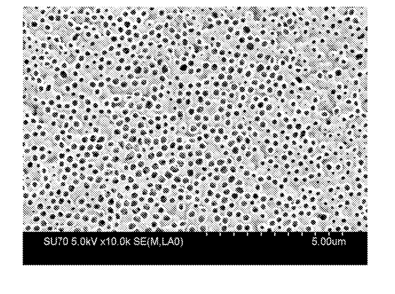
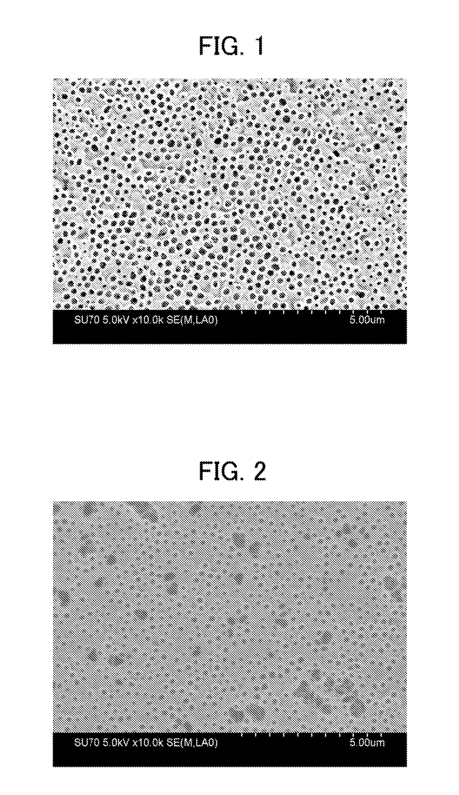
[0109]A porous polyimide film was formed as in Example 1 except that the volume ratio between the polyamide acid and the fine particles of the first varnish was adjusted to 34:66 (mass ratio: 25:75) and that the volume ratio between the polyamide acid and the fine particles of the second varnish was adjusted to 40:60 (mass ratio: 30:70). The surface on the side to which the first varnish was applied, which would be brought into contact with the negative electrode, was observed with an SEM. FIG. 3 shows the surface condition in Example 2.

[0110]It was demonstrated that a button battery according to Example 1 of the present invention shows a high capacity retention ratio at a high rate and has excellent electrical characteristics, compared to those of Comparative Examples. This is presumed to be caused by that a larger number of pores can be formed in the surface on the negative electrode side by forming two layers and to improve the Li ion mobility, compared to those in Comparative Ex...

example 3

[0112]A porous polyimide was formed as in Example 1 except that the thickness of the film formed from the first varnish was about 1 μm and that the total thickness of the unburned composite film was about 20 μm.


PUM

PropertyMeasurementUnit
porosityaaaaaaaaaa
volume fractionaaaaaaaaaa

Abstract

A method for producing a porous polyimide film comprises: forming a first un-burned composite film wherein the first film is formed on a substrate using a first varnish that contains (A1) a polyamide acid or a polyimide and (B1) fine particles at a volume ratio (A1):(B1) of from 19:81 to 45:65; forming a second un-burned composite film wherein the second film is formed on the first film using a second varnish that contains (A2) a polyamide acid or a polyimide and (B2) fine particles at a volume ratio (A2):(B2) of from 20:80 to 50:50 and has a lower fine particle content ratio than the first varnish; burning wherein an un-burned composite film composed of the first film and the second film is burned, thereby obtaining a polyimide-fine particle composite film; and a fine particle removal step wherein the fine particles are removed from the polyimide-fine particle composite film.

Description

TECHNICAL FIELD[0001]The present invention relates to a method for producing a porous polyimide film, a porous polyimide film, and a separator including the film.BACKGROUND ART[0002]In recent years, because of reductions in sizes of portable electronic devices and development of hybrid automobiles, electric automobiles, etc. due to consideration of environmental problems such as increases in atmospheric pollution and carbon dioxide, secondary batteries having excellent characteristics, such as high efficiency, high output, high energy density, and light weight are needed for such electronic devices and electric automobiles. Various secondary batteries having such characteristics have been developed and researched. Lithium secondary batteries have been also variously researched in order to provide ones having such characteristics.[0003]A chargeable and dischargeable lithium battery usually has a structure in which a space between a positive electrode (cathode) and a negative electrod...

Claims


Application Information

Patent Timeline
Patent Type & Authority Applications(United States)
IPC IPC(8): H01M10/052H01M50/403H01M50/414H01M50/423H01M50/449
CPCH01M2/1653H01M2/1686H01M2220/30H01M10/052H01M2220/20H01M2/145B01D71/64B32B27/34H01M10/0525B01D2323/18B32B5/16B32B27/281B32B2307/20B32B2457/10B32B2605/00B01D67/003B01D69/02B01D69/12B01D2323/12Y02E60/10Y02E60/50H01M50/446H01M50/449H01M50/403H01M50/414H01M50/423B01D2323/21813B01D69/1218B32B3/26B32B37/24H01M8/02H01M8/10B32B2037/246B32B2457/18Y02T10/70
Inventor SUGAWARA, TSUKASAASAI, TAKAHIRO
Owner TOKYO OHKA KOGYO CO LTD
Learn More